Illustrated guides · Biological treatment
How does an SBR perform several stages in one tank?
A sequencing batch reactor does not eliminate biological treatment or solids separation. It makes one variable-volume basin perform tasks in sequence through controlled filling, aeration, mixing, settling, decanting and wasting.
Direct answer
Direct answer
An SBR treats one batch through fill, react, settle, draw and idle/waste stages. During fill and react, retained activated sludge contacts the new wastewater; aerated and unaerated mixed periods can be arranged for carbon removal, nitrification and denitrification. Influent, aeration and strong mixing then stop so flocs settle in a quiescent basin. A decanter removes only the clarified upper layer, while settled biomass remains for the next cycle and wasting controls SRT. The process replaces separation in space with separation in time, so repeatable sequencing, level/valve control, reliable decanting and healthy sludge are essential.
Four conditions keep the time-separated process intact
Hydraulic or equipment actions leaking across stages can erase the functional boundary.
Influent and effluent obey stage boundaries
Conventional SBR settling and decanting need protection from disruptive inflow. Parallel basins, equalization or a purpose-designed continuous-inflow variant must handle continuous arrivals.
Aeration and mixing are separate controls
Aerated reaction supplies oxygen and mixing; unaerated mixing can create anoxic reaction; settling stops mixing that would disturb the blanket.
The decanter stays inside the clear-water layer
Intake elevation, descent, draw rate and scum exclusion must avoid the blanket and preserve enough biomass and volume for the next cycle.
Cycle, exchange volume and SRT stay balanced
Cycle length controls batch frequency, exchange volume controls batch flow, and wasting controls SRT. Changing one alters reaction and settling margins.
One basin becomes several unit processes through switchable equipment
The variable-volume basin contains mixed liquor, aeration, mechanical equipment and inlet/outlet lines whose states change during the cycle.
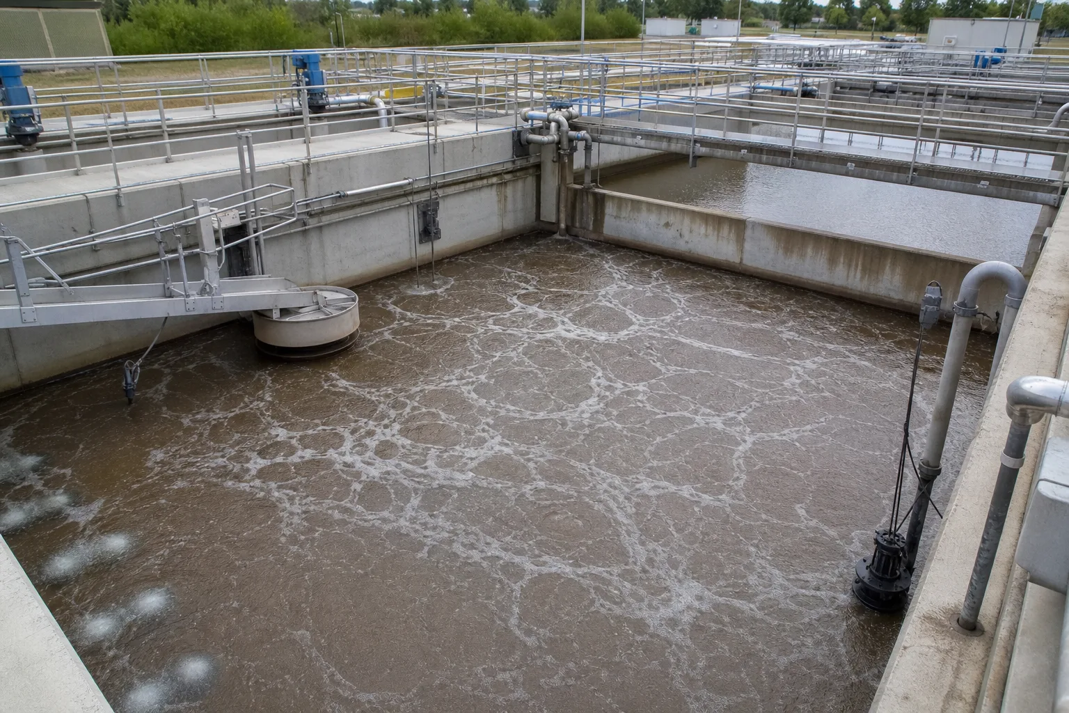 11Variable-volume basin22Bottom aeration and mixing33Floating/rotating decanter44Influent, level and valves
What to identify
- 1Variable-volume basin
- 2Bottom aeration and mixing
- 3Floating/rotating decanter
- 4Influent, level and valves
What the image proves
A single aeration basin is not automatically an SBR. Interlocked fill, react, settle, decant and wasting actions make it perform equalization, reaction and clarification in sequence.
How to verify on site
Match PLC trends for level, inlet valve, blower/mixer, decanter and wasting pump to one observed complete cycle.
Suspended flocs perform the biological reaction
Bubbles, suspended flocs, upper mixed liquor and gathering solids show how mixing creates contact and stopping disturbance begins separation.
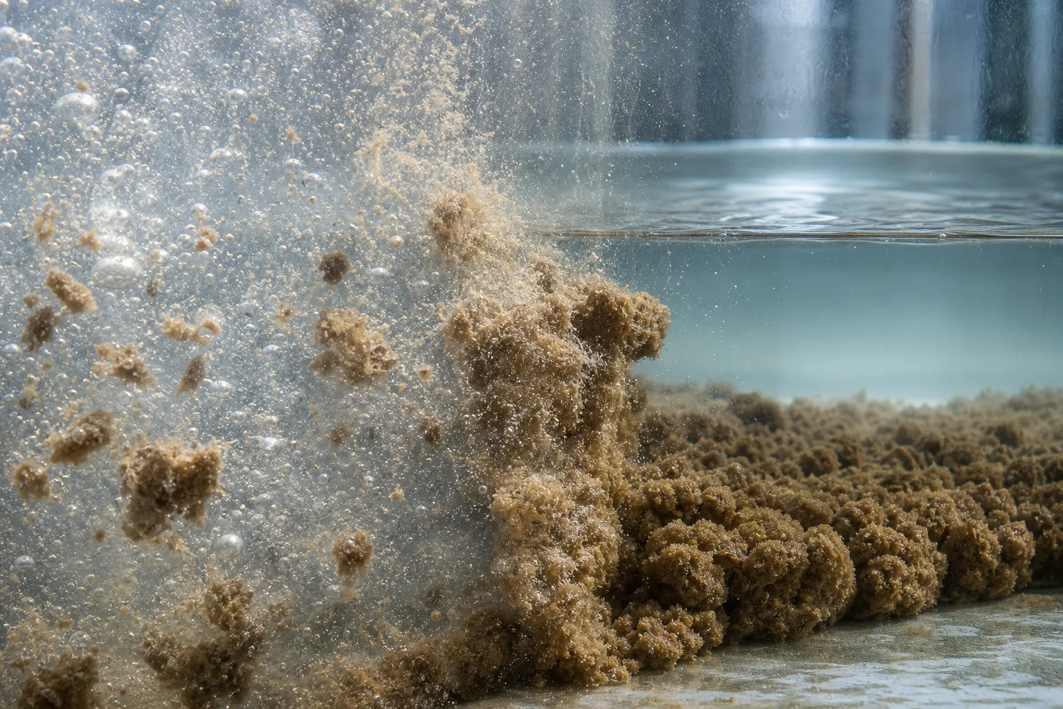 11Oxygen-transfer bubbles22Suspended activated-sludge flocs33Upper mixed liquor44Gathering sludge layer
What to identify
- 1Oxygen-transfer bubbles
- 2Suspended activated-sludge flocs
- 3Upper mixed liquor
- 4Gathering sludge layer
What the image proves
React does not always mean continuous aeration. Aerated periods remove carbon and nitrify; unaerated mixed periods can use carbon to denitrify.
How to verify on site
Plot DO, ORP, pH, ammonia, nitrate and aeration/mixing state on the same cycle timeline to confirm reaction endpoints.
Five vessels visualize five time states of the same basin
Side-by-side reactors make fill, aerated react, quiescent settle, clarified draw and idle/waste visible at once, although the real basin experiences them in time.
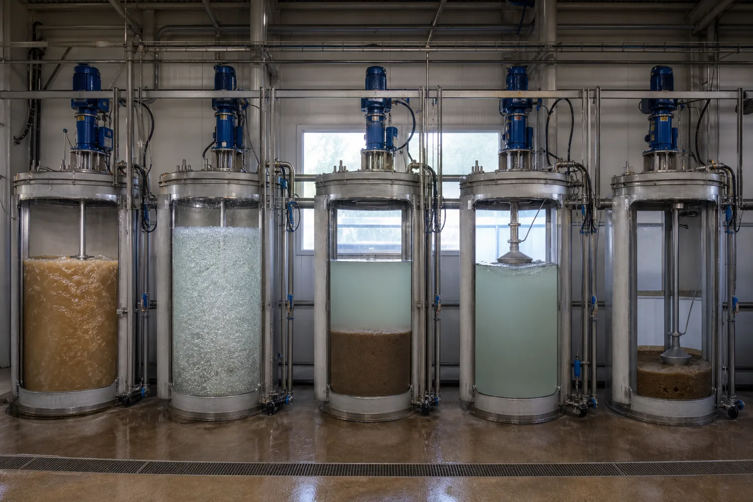 11Fill: level rises22React: aerate/mix33Settle: stop disturbance44Draw plus idle/waste
What to identify
- 1Fill: level rises
- 2React: aerate/mix
- 3Settle: stop disturbance
- 4Draw plus idle/waste
What the image proves
Every stage has permitted and prohibited equipment actions. Inflow, aeration or strong mixing during settle/draw can destroy separation.
How to verify on site
Build and test a stage-permission matrix for inlet, outlet, aeration, mixing, decanter, waste and bypass controls, including power-loss positions.
A stable interface must survive the transition from settle to draw
Aerated liquor, a compressed blanket under clear water, and a disturbed decant case show why good settling and good effluent are related but not identical.
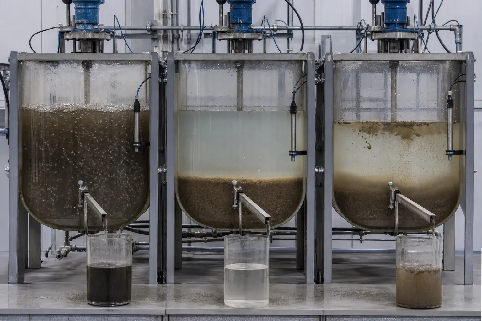 11Aerated mixed phase22Clear-water/sludge interface33Compressed sludge blanket44Solids carryover during draw
What to identify
- 1Aerated mixed phase
- 2Clear-water/sludge interface
- 3Compressed sludge blanket
- 4Solids carryover during draw
What the image proves
Even well-settled solids can be carried out by a high blanket, deep or fast draw, scum capture or decanter disturbance.
How to verify on site
Track interface height and settling before draw, then correlate decanter depth and instantaneous rate with turbidity/TSS throughout draw.
Diagnosis aligns samples, sensors, mechanisms and cycle trends
Different samples, a fouled probe, foam and decant equipment show why no single reading can explain an SBR upset.
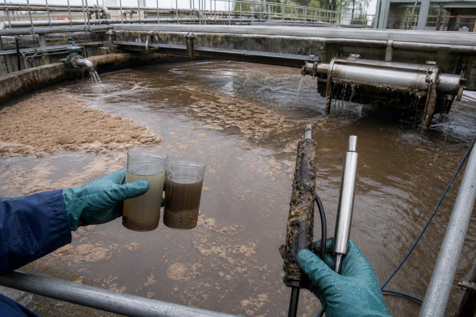 11Stage-specific samples22Fouled/drifting probe33Foam and sludge condition44Influent and decant equipment
What to identify
- 1Stage-specific samples
- 2Fouled/drifting probe
- 3Foam and sludge condition
- 4Influent and decant equipment
What the image proves
Level drift changes exchange volume, dirty DO/ORP probes can mis-time reaction, and valve or decanter faults can mix batches or export solids.
How to verify on site
Verify online sensors with portable/lab measurements, calibrate level against volume, test valve travel and decanter motion, and timestamp every sample.
Six handoffs for one batch
Each step defines water, oxygen, mixing, solids and equipment state.
1 Prepare cycle
Retained sludge + low water level
Reset equipment and retain biomass for the next batch.
2 Fill
Influent enters; level rises
Bring substrate into contact with retained sludge under static, mixed or aerated fill.
3 React
Aeration/mixing switches by program
Remove organics and arrange nitrification, denitrification or biological P removal.
4 Settle
Stop influent, aeration and strong mixing
Settle and compress flocs beneath a clear supernatant.
5 Draw
Supernatant → disinfection/discharge
Remove treated water without disturbing the blanket.
6 Idle and waste
Excess sludge → solids handling
Wait/equalize and control MLSS and SRT before restart.
Stage duties and cross-stage risks
A device may be required, optional or prohibited depending on the active stage.
Fill
- Primary duty
- Accept the batch and contact substrate with retained sludge
- Typical upset
- Excess flow, poor split or leaking inlet disturbs quiet stages
- Field evidence
- Batch volume, level slope, influent load, valve feedback and basin split
React
- Primary duty
- Use aerated/unaerated mixed periods to meet C-N-P goals
- Typical upset
- Insufficient time, oxygen, alkalinity, temperature or SRT
- Field evidence
- Cycle DO/ORP/pH and staged COD, NH₄, NO₂, NO₃ and phosphate
Settle
- Primary duty
- Create clear supernatant in a quiescent basin
- Typical upset
- Bulking, gas lift, residual mixing, influent leakage or short settling
- Field evidence
- Settle curve, SVI, blanket, supernatant turbidity and equipment state
Draw/idle/waste
- Primary duty
- Export supernatant, restore low level and control solids age
- Typical upset
- Deep/fast draw, scum intake, incorrect wasting or reset failure
- Field evidence
- Decanter path/rate, effluent TSS, low level, waste mass and alarms
The five-stage model is a common framework, not a mandatory fixed recipe. Fill may overlap reaction; nutrient removal may add anaerobic/anoxic/oxic sub-stages; continuous-inflow variants use baffles or special hydraulics. Judge the actual equipment and control narrative.
Align three evidence groups
Cycle and hydraulics
Stage times, high/low levels, exchange volume, instantaneous fill/draw flow, parallel-basin offset and overflow/bypass events.
Reaction and sludge
DO, ORP, pH, temperature, alkalinity, MLSS/MLVSS, SRT, SVI and staged COD, ammonia, nitrate, TN and phosphate/TP.
Equipment and effluent
Feedback/alarms from blowers, mixers, valves, level instruments, decanter and waste pump plus draw-period turbidity, TSS and volume.
How to localize common cycle upsets
- Combined signal
- Clear supernatant before draw, but TSS spikes during draw
- Suspect first
- Deep/fast decant, high blanket, scum intake or mechanical disturbance
- Next step
- Align decanter position/rate with turbidity, measure blanket and inspect the mechanism and scum exclusion
- Combined signal
- High end-of-react ammonia while indicated DO stays high
- Suspect first
- Low SRT, temperature/alkalinity limitation, inhibition or a falsely high fouled probe
- Next step
- Verify DO, pH/alkalinity, temperature, SRT, oxygen uptake and toxicity before adding air
- Combined signal
- One basin's level or batch volume drifts over cycles
- Suspect first
- Level drift, leaking valve, decanter travel or flow-split fault
- Next step
- Calibrate level-to-volume, leak-test valves and reconcile each batch mass balance with PLC states
- Combined signal
- Blanket floats with gas bubbles during settle
- Suspect first
- Denitrification in settled sludge
- Next step
- Check end-react nitrate/carbon, temperature and timing; improve anoxic reaction and draw window rather than merely settling longer
Four common misconceptions
One basin eliminates every other unit
Pretreatment, equalization, disinfection and solids handling may remain; continuous influent also needs buffering or alternating basins.
Set the five times once and leave them
Flow, load, temperature and sludge change, so cycle curves and effluent must keep validating the recipe.
No aeration means settling
Unaerated mixing supports anoxic reaction; settling also requires removal of disruptive mixing and hydraulics.
Cloudy effluent proves incomplete biology
Bulking, gas lift, a high blanket or poor decanting can export solids after reaction is complete.