Illustrated guides · Disinfection, oxidation, and micropollutants
Why are PFAS called forever chemicals?
Many PFAS contain highly fluorinated carbon chains shielded by strong C–F bonds, resisting conventional biological and oxidative breakdown while moving, accumulating, or forming from precursors.
Direct answer
Direct answer
PFAS are a large family of per- and polyfluoroalkyl substances, not one chemical, and members do not share identical persistence, mobility, or bioaccumulation. The “forever chemicals” label mainly reflects the resistance of many highly fluorinated carbon backbones: strong C–F bonds and a fluorine shell make complete defluorination difficult for hydrolysis, sunlight, microbes, chlorine, ozone, UV, or conventional hydroxyl-radical treatment. Some polyfluorinated precursors do transform, but often into shorter or more stable terminal perfluoroalkyl acids rather than carbon dioxide and inorganic fluoride. A parent compound can fall while terminal acids rise—transformation, not destruction. Fluorinated tails and charged/polar heads also give PFAS unusual interfacial behavior. Longer-chain compounds often sorb more strongly to GAC, resins, soil, or proteins; shorter-chain compounds are generally more mobile and break through sorbent beds earlier, not harmless. Proven GAC, anion exchange, and NF/RO barriers mainly transfer PFAS from water into spent media or concentrate. They can protect finished water but do not automatically break C–F bonds. A complete project therefore links source reduction, target/precursor analysis, compound-specific breakthrough, and compliant storage, transport, reactivation, destruction, or disposal of PFAS-bearing residuals.
Four boundaries explain what “forever” means
It is not one molecule frozen forever; stability, precursor transformation, partitioning, and residual management combine.
A strong C–F framework resists defluorination
Highly fluorinated chains resist acids, bases, mild oxidation, and most metabolism. Loss of a parent peak does not prove conversion to CO₂ and inorganic fluoride.
Precursors can form persistent terminal acids
Some PFAS transform into terminal PFAAs. A short target list can show an apparent increase after treatment because hidden precursor mass became measurable.
Chain and head group control fate
Sorption, protein binding, and mobility differ by chain length and sulfonate/carboxylate or other head groups. PFOA/PFOS cannot represent the whole family.
Removal is not destruction
GAC/resin moves PFAS into solids and NF/RO into concentrate. Poor residual management simply relocates the release.
A PFAS pilot train links adsorption, ion exchange, membrane separation, and residuals
Dark left columns provide GAC adsorption, central vessels can hold PFAS-selective resin, horizontal pressure tubes are NF/RO, and foreground containers separate feeds, products, and residuals.
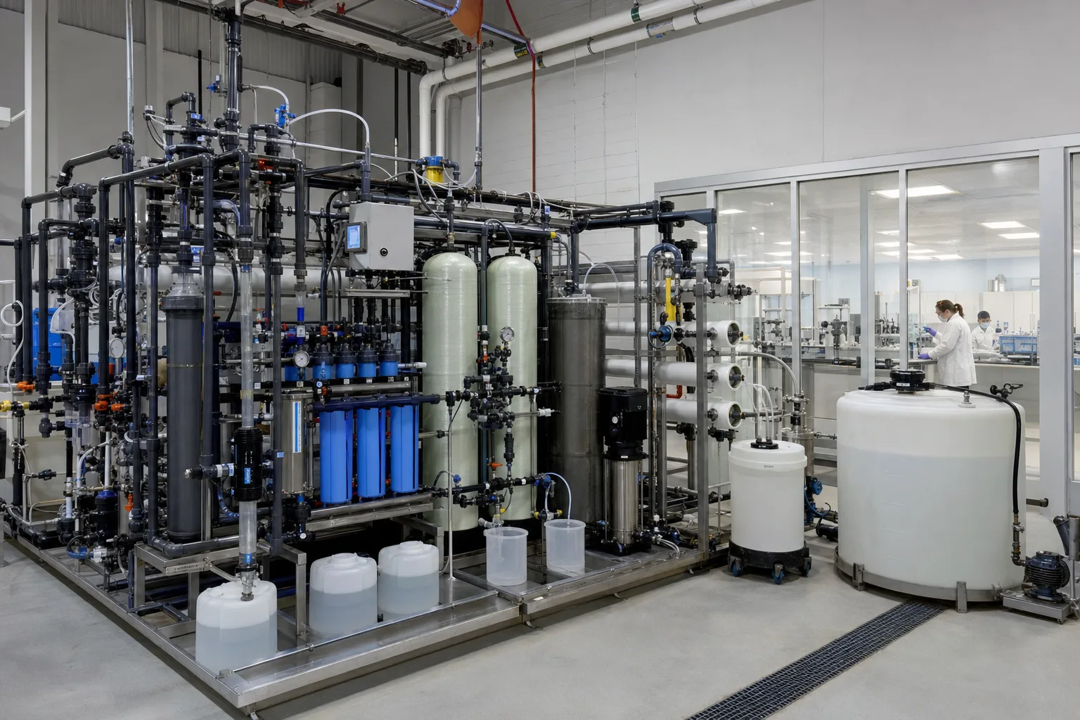 11GAC pre-adsorption bed22PFAS-selective anion-exchange bed33NF/RO high-pressure membrane stage44Product, concentrate, and spent-media boundary
What to identify
- 1GAC pre-adsorption bed
- 2PFAS-selective anion-exchange bed
- 3NF/RO high-pressure membrane stage
- 4Product, concentrate, and spent-media boundary
Figure takeaway
All three barriers can reduce PFAS in product water by different mechanisms and create different residuals. Select combinations by target list, short-chain breakthrough, competitors, recovery, and residual destination—not a single removal percentage.
How to verify it in the field
Time-align feed, interstage, product, concentrate/spent-media targets and flows. Estimate mass balance and record bed volumes, pressure, recovery, media batch, and residual route.
Trace PFAS analysis needs a defined method, isotope dilution, and strict blank control
An analyst adds internal standard to a cleaned vial; the autosampler holds field, blank, and QC samples; liquid chromatography separates targets before tandem mass spectrometry quantifies ion transitions.
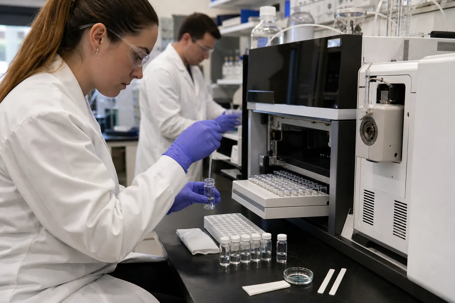 11Sample vial, isotope standards, blanks22Autosampler and QC sequence33Liquid-chromatography separation44Tandem mass-spectrometry detection
What to identify
- 1Sample vial, isotope standards, blanks
- 2Autosampler and QC sequence
- 3Liquid-chromatography separation
- 4Tandem mass-spectrometry detection
Figure takeaway
‘No PFAS detected’ only means the method-list compounds were below reporting limits in that sample. It does not prove absence of all PFAS or precursors. Fluorinated equipment and laboratory background can contaminate trace results.
How to verify it in the field
Use method-compatible containers and a contamination plan. Review field/trip/method blanks, duplicates, spikes, isotope recovery, calibration, reporting limits, and peak confirmation. Do not substitute one total-fluorine screen for compound data.
Side-by-side GAC, anion exchange, and membranes show three capture pathways
Black GAC uses pores and interfacial interactions, amber resin uses positive sites for anionic PFAS, and the pressure membrane rejects solutes into concentrate.
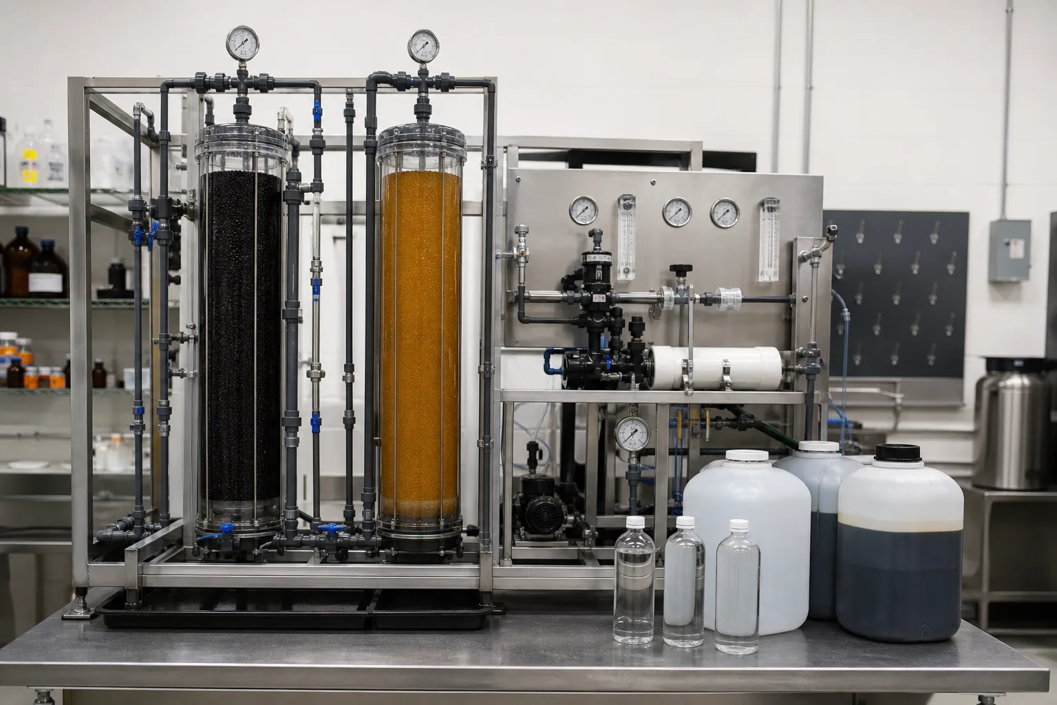 11GAC: pore/interfacial sorption22AIX: positive sites bind anionic PFAS33NF/RO: charge/size/solution-diffusion rejection44Product and PFAS-bearing concentrate samples
What to identify
- 1GAC: pore/interfacial sorption
- 2AIX: positive sites bind anionic PFAS
- 3NF/RO: charge/size/solution-diffusion rejection
- 4Product and PFAS-bearing concentrate samples
Figure takeaway
Longer-chain PFAS usually remain on GAC longer. Selective AIX can increase capacity but faces organic/inorganic competition. High-pressure membranes cover more short-chain compounds but leave a concentrate requiring management.
How to verify it in the field
Compare individual compounds; record NOM, sulfate/nitrate, EBCT, depth, membrane flux/recovery, cleaning streams, and concentrate route. Validate on actual water.
Parallel media columns plus LC-MS/MS reveal compound-specific breakthrough orders
Columns contain different GACs, resin, or controls under one feed and separate flows; the analyzer measures sequential samples to build curves versus bed volumes.
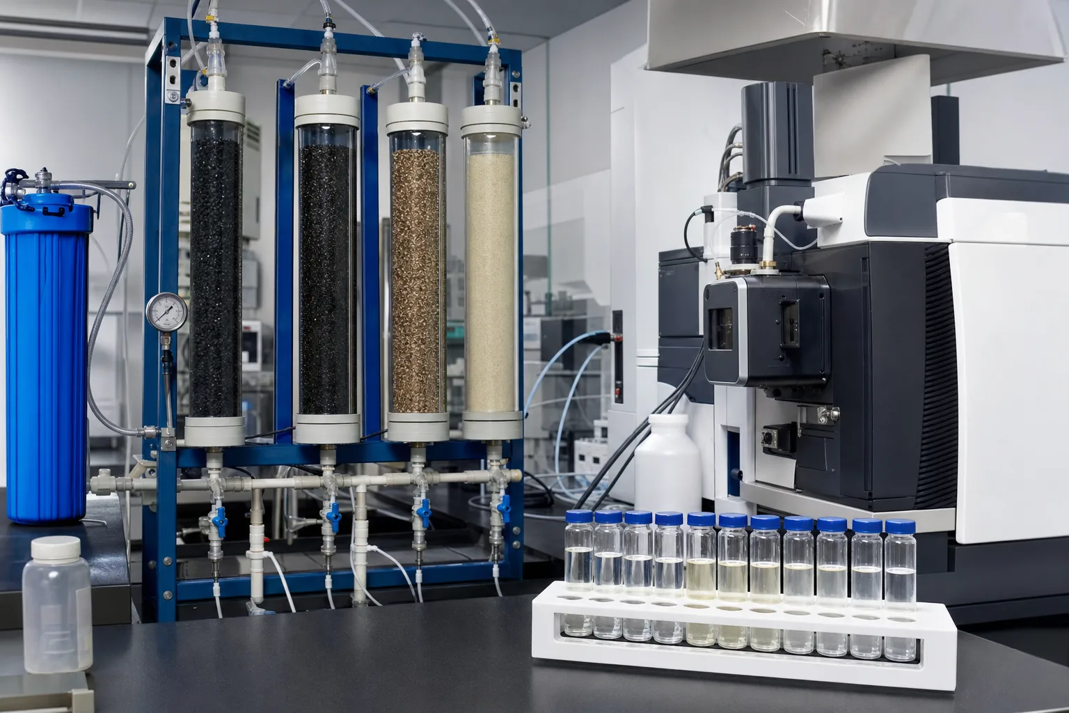 11Common feed and independent flow control22Contrasting GAC pore structures33PFAS-selective resin/control media44Compound breakthrough samples and LC-MS/MS
What to identify
- 1Common feed and independent flow control
- 2Contrasting GAC pore structures
- 3PFAS-selective resin/control media
- 4Compound breakthrough samples and LC-MS/MS
Figure takeaway
There is no single PFAS breakthrough curve. Short carboxylates, sulfonates, long chains, and precursors appear differently; TOC or one PFOA/PFOS result cannot protect every target.
How to verify it in the field
Plot C/C₀ for each target against time, bed volumes, and loading. Hold feed/flow consistent, track NOM/anions, and set monitoring/changeout on the earliest risk-relevant compound.
Field sampling and cartridge removal extend the treatment boundary to PFAS-bearing residuals
One worker samples the train while another places a used cartridge in a lined container; closed drums segregate spent media, rinse water, and contaminated supplies.
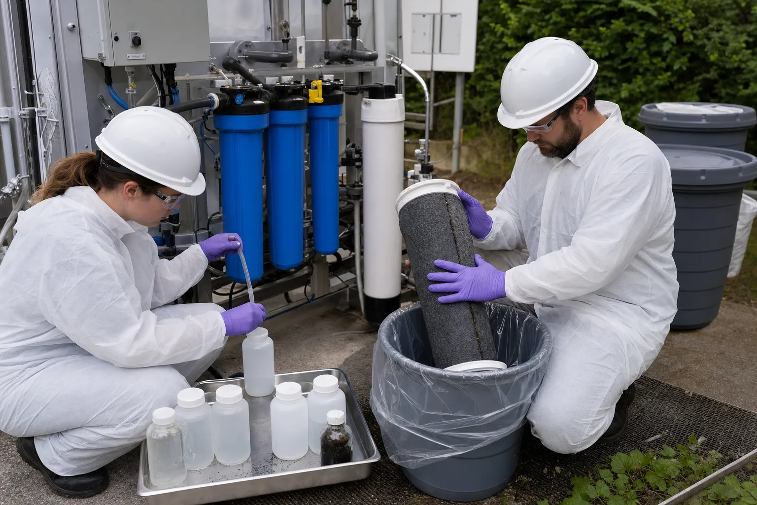 11Feed/interstage/product sample ports22Trace samples and field blanks33Used PFAS-bearing cartridge/media44Labeled segregated residual containers
What to identify
- 1Feed/interstage/product sample ports
- 2Trace samples and field blanks
- 3Used PFAS-bearing cartridge/media
- 4Labeled segregated residual containers
Figure takeaway
Removing a cartridge concentrates PFAS into a smaller mass; it does not erase them. Media, membranes, backwash/rinse water, concentrate, and contaminated PPE belong in the project mass boundary.
How to verify it in the field
Document compatible closed containers, labels, weights/volumes, custody, and destination. Use current authority requirements for reactivation, destruction, or disposal and verify releases/mass where applicable.
Six PFAS mass links from use to residual endpoint
Every transfer must be distinguished from destruction.
1 Release
Manufacture/foam/product/waste → water/soil/air
Find and reduce continuing sources.
2 Partition
Short chains move; longer chains sorb/bind
Map fate by structure.
3 Transform
Polyfluorinated precursor → terminal PFAA
Expose hidden mass without claiming destruction.
4 Analyze
Samples/blanks → SPE-LC-MS/MS
Quantify a defined method list.
5 Capture
GAC/AIX/NF-RO → media/concentrate
Protect water and close transfer mass.
6 End point
Validated technology/facility → long-term control
Prevent rerelease from residuals.
Four functional parts of a PFAS project
Source, analysis, separation, and residual endpoint require separate evidence.
Source/conceptual model
- Role
- Map chemicals, precursors, continuing sources, and pathways
- Typical failure
- End-of-pipe only; ongoing AFFF/industry/leachate load missed
- Evidence
- History, up/down-gradient data, flow/load, precursor/non-target clues
Sampling/laboratory
- Role
- Reliably quantify method targets at trace levels
- Typical failure
- Fluorinated contamination, failed blanks, wrong list/limits
- Evidence
- Method fit, blanks/recovery/calibration, isotope standards, custody
Water barrier
- Role
- Use GAC/AIX/NF-RO to meet product goals
- Typical failure
- Short-chain breakthrough, competition, membrane leak/recovery shift
- Evidence
- Compound curves, BV/EBCT, competitors, flux/rejection/concentrate
Residual endpoint
- Role
- Manage media, concentrate, rinse, and destination
- Typical failure
- Separation called destruction; storage/transport/disposal rereleases
- Evidence
- Mass balance, batch/weight/volume, manifests, facility/release verification
PFAS definitions, target lists, drinking-water limits, waste classifications, and acceptable destruction/disposal routes vary by jurisdiction and change over time. Use current applicable requirements and validated methods. Targeted methods do not cover all PFAS; total-organofluorine screens are not specific-compound concentrations.
Put three evidence groups into one mass balance
Water, compounds, precursors
Source/flow, target PFAS, chain/head group, likely precursors, NOM/DOC, inorganic anions, pH, temperature, and season.
Barrier and breakthrough
GAC/AIX bed volumes, EBCT, headloss, media batch and C/C₀; NF/RO flux, recovery, integrity, product and concentrate flow/concentration.
Analytical QC and endpoint
Blanks, isotope recovery, reporting limits, sample batch; media/concentrate/rinse mass, storage, shipment, reactivation/destruction/disposal, and release verification.
Separate transformation, breakthrough, and analytical artifacts
- Combined signal
- Short chains rise first after GAC while long chains remain low and hydraulics are stable
- Likely cause
- Compound-selective breakthrough
- Next step
- Increase short-chain monitoring; check NOM/BV and adjust media, lead-lag beds, or changeout trigger
- Combined signal
- Several PFAS break early on AIX as sulfate/nitrate or organics rise
- Likely cause
- Competitive loading or resin/bed change
- Next step
- Run current-water columns and verify resin batch, depth/EBCT, and competing ions
- Combined signal
- RO product is low, concentrate high, and mass approximately closes
- Likely cause
- Successful separation, not destruction
- Next step
- Verify concentrate flow/destination and membrane integrity; include endpoint in compliance and cost
- Combined signal
- Oxidation lowers parent but raises terminal short acids, or blanks/isotopes fail
- Likely cause
- Precursor transformation or analytical contamination/matrix effect
- Next step
- Resolve QA/QC, expand targets/precursors and fluorine screening; do not claim complete destruction
Four common misconceptions
PFAS is one molecule that never changes
It is a diverse family; precursors transform and members differ in fate and accumulation.
Any fluorine is PFAS, including fluoride in water
PFAS are organic fluorinated structures; inorganic fluoride is a different chemical form.
Strong ozone, UV, or AOP must destroy PFAS
Under conventional conditions parent change is not complete defluorination, and many PFAS resist these processes.
GAC, resin, or RO ends the environmental problem
They mostly separate and concentrate; the residual endpoint controls rerelease.