Illustrated guides · Physicochemical treatment
How does a sand filter capture particles and backwash itself?
A rapid granular filter passes coagulated and clarified water downward through sand, anthracite, or mixed media, captures particles by transport and attachment within pore paths, then reverses clean water and optional air through the bed to detach and remove the accumulated solids.
Direct answer
Direct answer
A rapid sand, dual-media, or multimedia filter is not a fixed-pore sieve. Microfloc from upstream treatment follows tortuous paths through the bed and is intercepted, settles, collides with, and attaches to media grains. Some solids load the upper zone while a well-designed bed also uses depth. As deposits constrict pores, head loss and local velocity rise and flow seeks lower-resistance paths; continued operation can produce breakthrough, cracks, short-circuiting, or the terminal allowable head loss. Backwash should start from defined individual-filter criteria such as effluent turbidity or particle count, bed head loss, run time, or production. The filter is isolated, surface wash or air scour is applied when designed, and clean water moves upward through the underdrain to expand the media uniformly, rub grains, detach solids, and carry them to wash-water troughs. The bed then resettles and may be rested, slow-started, and filtered to waste until its own effluent is acceptable. Underwashing leaves mudballs, binding, and dead zones; overwashing can lose media, disturb support gravel, or damage underdrains. Operators therefore need individual-filter flow, head loss, turbidity/particles, bed expansion, distribution, wash-water quality, and recycle evidence rather than a timer alone.
Four links that must work in both filtration and backwash
Clear effluent now or a visibly turbulent wash does not prove that the bed is uniform or that retained solids actually left.
Pretreatment creates filterable microfloc
Unstable fines pass through when coagulation is weak; oversized fragile floc blinds the surface or breaks. pH, chemicals, mixing, clarified-water quality, and flow swings set the incoming burden.
Media and flow use bed depth
Grain size, density, grading, depth, and filtration rate set pore paths, shear, and solids distribution. A thick surface mat builds head loss early; cracks or media loss create shortcuts.
Backwash distribution produces the right expansion
The underdrain and air grid must loosen the whole bed. Water temperature and media properties change the required rate; too little leaves mudballs, while too much can lose media or upset support layers.
Return to service protects the clear-water system
Media must resettle and ripen while valves change gradually. Filter-to-waste, delayed start, or slow start should end on individual-filter turbidity or particle evidence under the plant SOP.
A filter bank can keep cells online while one cell backwashes
Headers and valves control each bay; a calm bay represents filtration, the turbulent bay represents wash, and the front overflow removes dirty wash water.
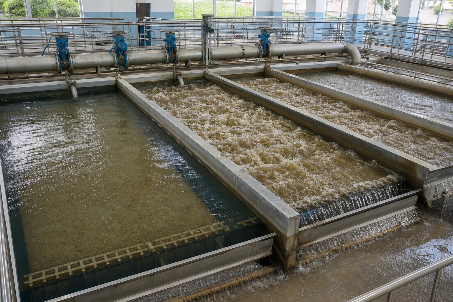 11Headers and isolation valves22Online filtering cell33Turbulent backwash cell44Wash trough and waste overflow
What to identify
- 1Headers and isolation valves
- 2Online filtering cell
- 3Turbulent backwash cell
- 4Wash trough and waste overflow
Figure takeaway
Filters operate as a bank. When one cell washes, its flow shifts to the remaining cells; without a plant-flow reduction, they can be bumped into overload and pass particles.
How to verify it in the field
Trace valve sequence and actual flow. Log each cell's rate, levels/head loss, and effluent turbidity; during wash, verify the load on remaining cells, wash flow, and even trough overflow.
A loaded column shows capture and head loss developing through depth
Darker attached solids occupy the upper bed while side pressure taps compare head at several elevations; cleaner lower media shows why total differential pressure alone cannot describe distribution.
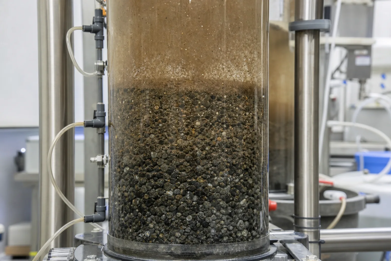 11Segment pressure taps22High-solids upper zone33Continued depth capture44Local head loss and flow shift
What to identify
- 1Segment pressure taps
- 2High-solids upper zone
- 3Continued depth capture
- 4Local head loss and flow shift
Figure takeaway
Filtration is not only surface screening. A sound bed uses depth; rapid surface blinding raises head loss early, while poor effluent at modest head loss points toward weak microfloc, cracks, or short-circuiting.
How to verify it in the field
Plot individual-filter head loss, rate, and effluent turbidity/particles against run time. Use segment pressures when available and depth samples to confirm where solids accumulated.
Filtration flows down and backwash flows up through the same bed
The left column holds a stationary layered bed during downflow; the right sends wash water and air from below, expands the media, and carries detached solids out at the top.
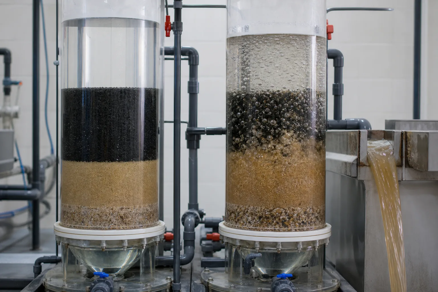 11Downflow through a fixed bed22Media and support layers33Upflow wash water/air scour44Expanded bed and dirty wash water
What to identify
- 1Downflow through a fixed bed
- 2Media and support layers
- 3Upflow wash water/air scour
- 4Expanded bed and dirty wash water
Figure takeaway
The aim is not maximum agitation. Backwash must detach and lift solids to the trough without losing media, rearranging support layers, or damaging the underdrain.
How to verify it in the field
Record surface-wash, air-scour, and low/high water-wash sequence, time, and rate. Measure temperature, resting depth, maximum expansion, whole-bed motion, and media in the trough.
Three columns separate underwash, an effective window, and over-wash
The left has clumps and uneven channels, the center is uniform with clearer supernatant, and the right is violently expanded toward media loss—three outcomes that a shared wash time can hide.
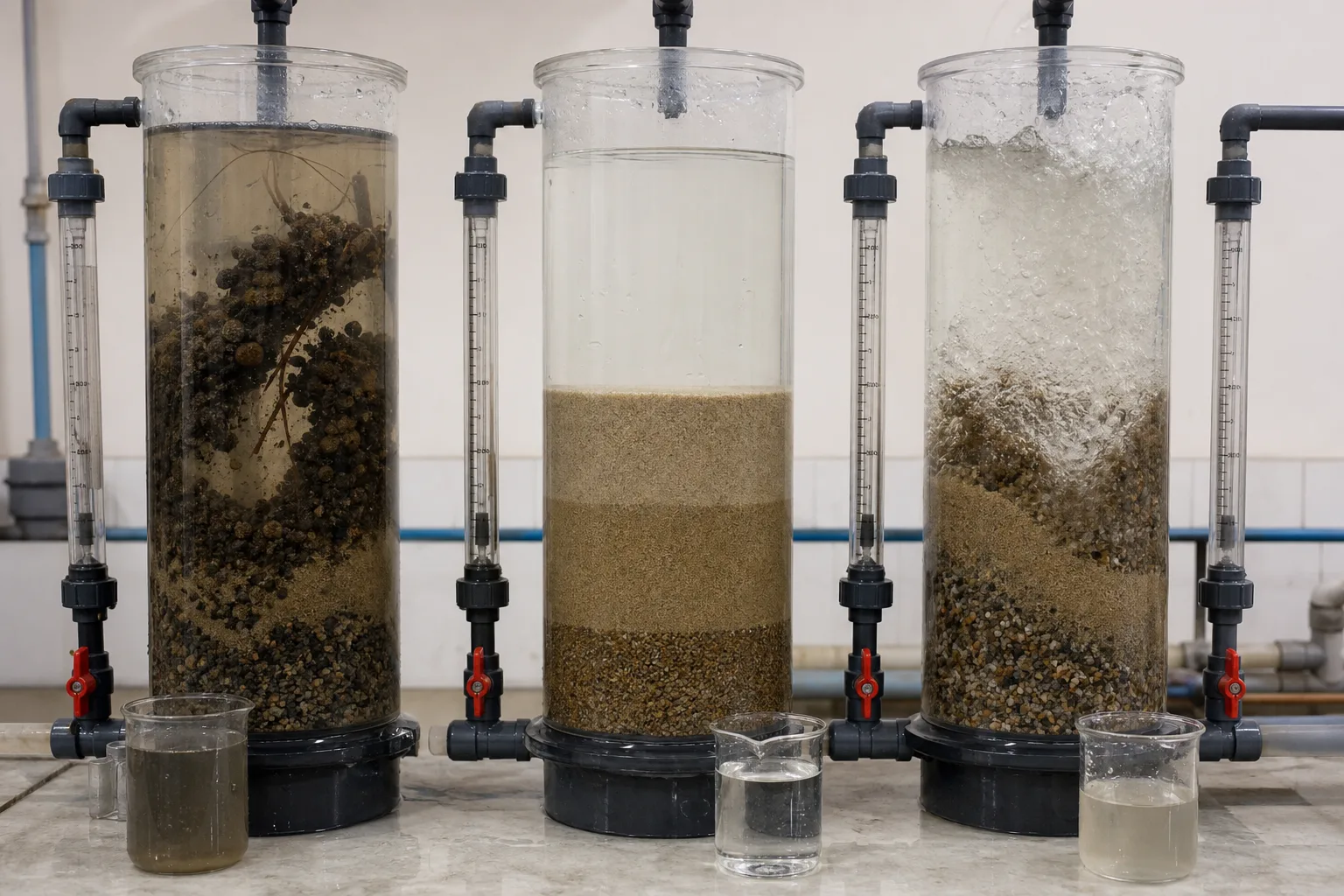 11Mudballs, binding, and channels22Uniformly cleaned bed33Over-expansion and media-loss risk44Post-wash samples and media loss
What to identify
- 1Mudballs, binding, and channels
- 2Uniformly cleaned bed
- 3Over-expansion and media-loss risk
- 4Post-wash samples and media loss
Figure takeaway
Identical wash duration can produce different cleaning. The operating window depends on temperature, grain density and size, depth, water/air rate, and distribution.
How to verify it in the field
Probe before and after, compare turbidity/particles, and measure rise rate and expansion. Track mudballs, media elevation, backwash solids, and first filtrate rather than judging surface turbulence alone.
A drained inspection finds mudballs, cracks, and dead zones hidden online
Operators inspect the exposed surface and localized clumps, then keep media cores from different positions separate; elevations and exposed hardware help trace uneven wash or media loss.
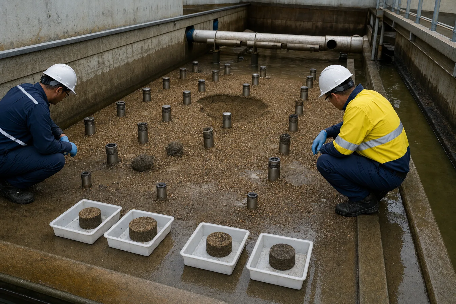 11Grid-based operator inspection22Surface elevation and cracks33Mudball or localized binding44Multi-location media cores
What to identify
- 1Grid-based operator inspection
- 2Surface elevation and cracks
- 3Mudball or localized binding
- 4Multi-location media cores
Figure takeaway
Total head loss and combined effluent can hide local defects. Mudballs, depressions, cracks, uneven depth, or support problems create repeatable shortcuts and require an offline grid inspection.
How to verify it in the field
Map media elevation, depth, cracks, depressions, mudballs, and sand in the clearwell. Link samples to the wash-distribution map, underdrain/nozzle inspection, and media addition history.
Six steps from incoming particles to removed backwash solids
Separate filtration, run termination, cleaning, and restart to locate the failed link.
1 Pretreat
Raw water → filterable microfloc
Create particles that attach without immediately blinding the surface.
2 Filter down
Water ↓ media → underdrain
Capture particles through bed depth and produce low-turbidity water.
3 End the run
Head loss/turbidity/particles/time → isolate
Stop before breakthrough or terminal head loss.
4 Loosen and detach
Air/surface wash + wash water ↑
Expand uniformly and break retained deposits free.
5 Remove solids
Dirty wash water → trough/residuals
Carry solids out and manage any recycle.
6 Resettle and ripen
Rest/slow start/filter-to-waste → service
Keep the initial turbidity spike out of finished water.
Responsibilities of four subsystems
Media does not act alone; pretreatment, bed hydraulics, washing, and restart constrain one another.
Coagulation/flocculation/clarification
- Main job
- Control the amount, size, strength, and surface of particles reaching filters
- Typical failure
- Unstable fines pass, weak large floc blinds the surface, or a solids surge overloads
- Evidence
- Raw/settled turbidity and particles, pH/chemicals, floc, filter loading
Media and operating flow
- Main job
- Provide attachment surface and bed depth while distributing filtration
- Typical failure
- Wrong grading/depth, media loss, cracks, excessive rate, or maldistribution
- Evidence
- Cell flow, head-loss curve, effluent, media elevation/grading, depth cores
Underdrain, air, and backwash
- Main job
- Distribute water/air, loosen the bed, and transport solids out
- Typical failure
- Dead zones, mudballs, underwash, over-wash, support or nozzle damage
- Evidence
- Flow/pressure, temperature, expansion, surface pattern, waste solids, media loss
Valves, filter-to-waste, residuals
- Main job
- Switch safely, control initial spikes, and manage dirty wash water
- Typical failure
- Surge/air binding, fast loading, poor first filtrate, or recycle shock
- Evidence
- Valve sequence, slow-start curve, cell turbidity/particles, waste quality and recycle rate/location
Backwash rate and expansion must be verified for the installed media, equipment, and water temperature. Typical expansion ranges in guidance are review starting points, not replacements for design criteria, manufacturer limits, local rules, and measured rise-rate/expansion tests.
Put three evidence groups on one filter-run timeline
Influent and loading
Flow, clarified-water turbidity/particles, temperature, pH/chemicals, floc condition, and actual rate of every online filter.
Bed response
Cell inlet/outlet level, total and segment head loss, effluent turbidity/particles, run time, valve position, and rate changes.
Wash and restart
Air/water flow and pressure, sequence, temperature, expansion/distribution, waste quantity/quality, media loss, filter-to-waste, and first filtrate.
Diagnose filter trouble from combined signals
- Combined signal
- Head loss rises quickly while individual-filter effluent stays clear
- Suspect first
- High solids or weak large floc, surface blinding, high rate, or incomplete prior wash
- Next step
- Align clarified-water and run curves, inspect the surface and wash pattern, then adjust pretreatment/load or cleaning—not only the timer
- Combined signal
- Turbidity/particles break through at modest head loss or in a sudden spike
- Suspect first
- Poor destabilization, media crack/short circuit, media loss, or valve/flow shock
- Next step
- Check cell rate and chemistry, compare effluent locations, then inspect media/underdrain and event logs
- Combined signal
- Parts of the bed stay still while others erupt and mudballs recur
- Suspect first
- Blocked/damaged distribution, uneven support, inadequate flow, or mismatched air-water sequence
- Next step
- Map bed motion, rise rate, and expansion; drain, grid-probe, and repair distribution components
- Combined signal
- An initial turbidity spike follows immediate return to service and then decays
- Suspect first
- No resettling/ripening, incomplete wash, rapid loading, or valve disturbance
- Next step
- Use evidence-ended filter-to-waste, rest and slow start, while confirming wash endpoint and valve sequence
Four misconceptions
Sand filters only sieve through grain gaps
Particles also collide, attach, and settle along tortuous pores; pretreatment and surface interactions matter as much as openings.
A fixed timer is the safest backwash trigger
Time cannot represent changing solids load or bed condition; combine individual-filter head loss, turbidity/particles, and operating limits.
A harder backwash is always cleaner
Over-expansion can lose media, disturb supports, or damage distribution; the goal is uniform detachment and removal.
Clear wash water means immediate service
Media still must resettle and ripen, and first filtrate can spike; restart should be controlled by individual-filter evidence.