Illustrated guides · Physicochemical treatment
Why is a high-rate clarifier faster than a conventional clarifier?
High-rate clarification does not simply accelerate the water. It increases floc settling velocity with dense or ballasted solids, then increases projected settling area per footprint with inclined plates or tubes.
Direct answer
Direct answer
High-rate clarifier is a family name, not one vessel geometry. Common arrangements include inclined-plate/tube settlers, solids-contact or dense-sludge clarifiers, and ballasted flocculation using microsand, magnetite, or recycled sludge. They gain capacity in two main ways. Coagulant first destabilizes colloids, while polymer attaches particles to ballast or a concentrated recycled-solids seed, producing denser, faster-settling floc. Inclined modules then divide a deep basin into short settling paths and provide far more horizontal projected area than the footprint alone. Water passes rapid mix, maturation, and clarification; heavy floc settles to a hopper or thickening zone, and clarified water rises between plates to level launders. Carrier-bearing underflow may pass through a hydrocyclone for media recovery, while dense sludge may be recycled directly and excess solids wasted. Some ballasted systems can treat flows far above conventional rates under matched conditions, but speed is conditional: pH, dose, sequence, mixing shear, maturation, carrier inventory, projected-area loading, distribution, sludge level, wasting, and plate cleanliness all have to work together. The process removes suspended and coagulated particulate matter; it does not automatically remove dissolved salts, ammonia, or poorly coagulable dissolved organics.
Four conditions create genuine high-rate capacity
Adding plates or increasing chemical dose alone does not preserve effluent quality at high loading.
Create floc that can actually settle
Rapid mix destabilizes particles; controlled maturation binds microfloc to polymer, microsand, or return sludge. Dose order, pH, alkalinity, and residence time set density and shear resistance.
Use projected area to shorten the path
Plates are not filter media. A particle reaches a nearby surface and slides down. Capacity still depends on horizontal projected area, spacing, angle, upward-flow distribution, and settling velocity.
Maintain carrier and solids inventory
Media loss, poor cyclone recovery, dilute return sludge, or uncontrolled wasting makes floc lighter. A media/solids mass balance matters more than one clear effluent sample.
Keep inlet, outlet, and sludge removal uniform
Short-circuiting overloads part of the module; fouling takes area offline; high sludge blankets re-entrain solids. Distribution, level launders, scraping, wasting, and cleanable plates protect real capacity.
A full-scale unit compresses reaction, plates, effluent collection, and solids recovery
Small basins on the left mix and mature floc, the green inclined pack provides projected settling area, the upper saw-tooth weir collects water, and pumps/cyclone equipment on the right recover solids or carrier.
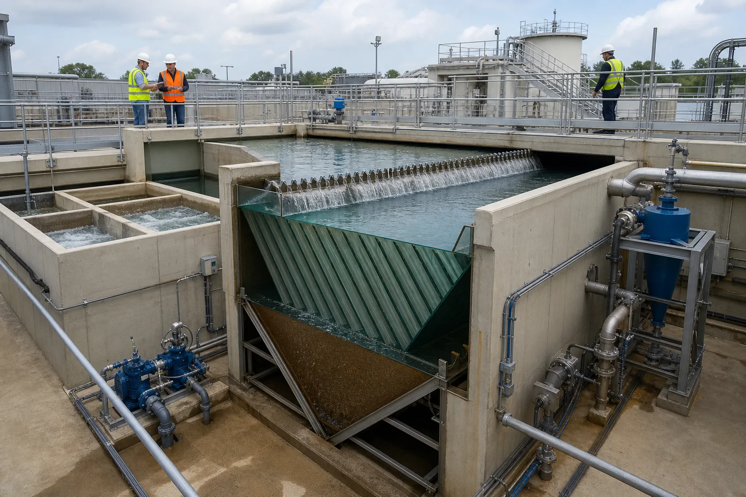 11Rapid-mix and maturation zones22Inclined plate pack33Level effluent weir44Sludge/carrier recovery skid
What to identify
- 1Rapid-mix and maturation zones
- 2Inclined plate pack
- 3Level effluent weir
- 4Sludge/carrier recovery skid
Figure takeaway
The footprint shrinks because particle weighting, short-path settling, thickening, and recycle form one continuous loop. If one function is offline, nominal high rate becomes actual solids carryover.
How to verify it in the field
Walk the flow path and verify levels, mixers, and valves. Trend feed/effluent turbidity or TSS, detention, plate-zone rise rate, weir load, blanket level, return/waste flow, and media makeup.
Microsand or return sludge gives floc a seed and weight
In the clear reactor, a paddle maintains contact and chemical enters above. Destabilized particles bridge into visible dense aggregates and settle quickly.
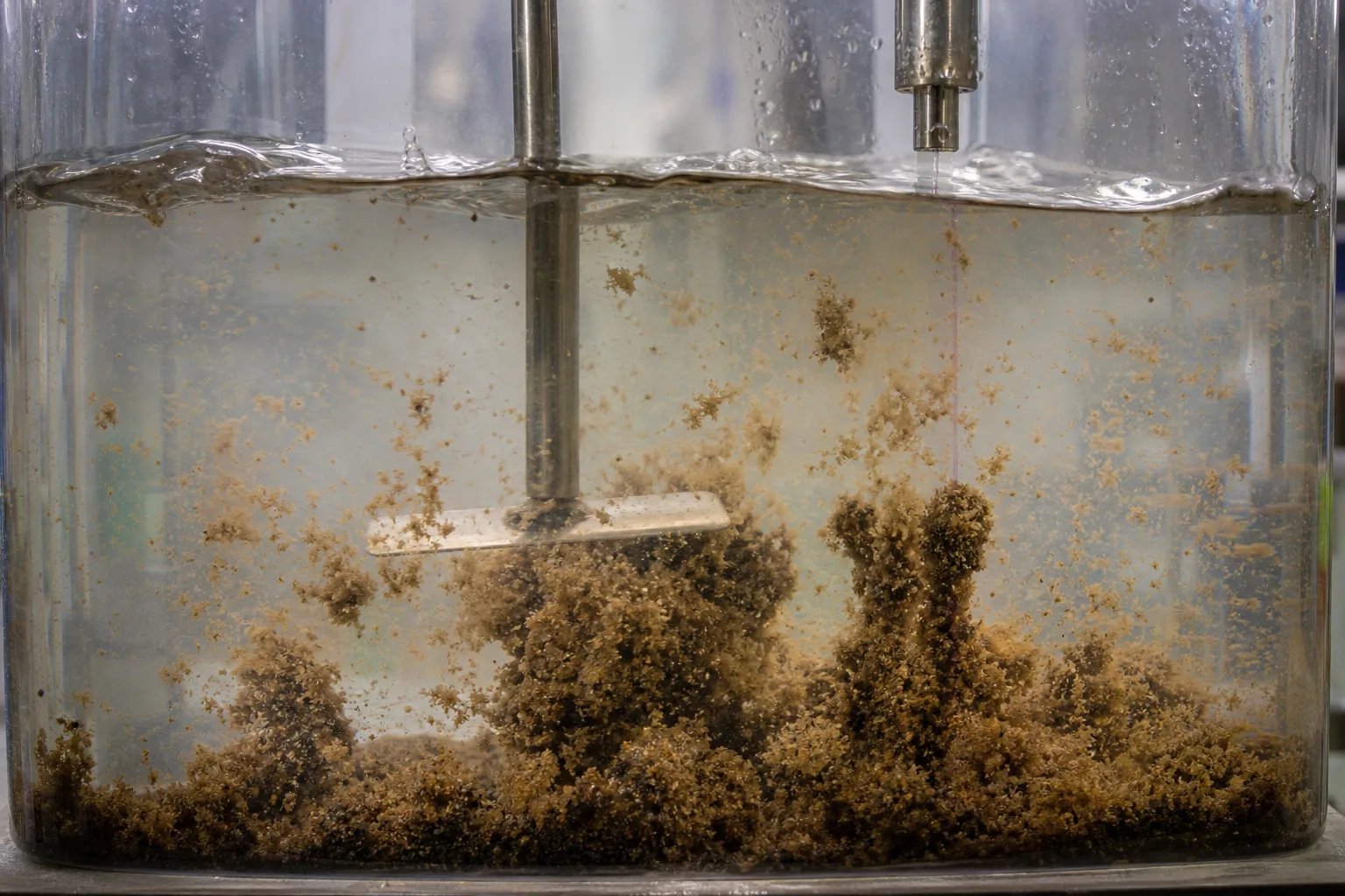 11Controlled-shear mixer22Polymer/chemical feed33Dense ballasted floc44Clarified upper zone
What to identify
- 1Controlled-shear mixer
- 2Polymer/chemical feed
- 3Dense ballasted floc
- 4Clarified upper zone
Figure takeaway
The first gain comes from changing the particle, not from the plates. Coagulant destabilizes, polymer bridges, and microsand or return sludge supplies seed area and density; these roles are not interchangeable.
How to verify it in the field
Run feed-and-return-water dose gradients. Record pH, sequence, G, maturation time, settling velocity, and shear recovery; use microscopy or sieving to confirm carrier incorporation.
A continuous pilot links dosing, maturation, lamella settling, and underflow recovery
From left to right the skid shows rapid mix, floc maturation, inclined-plate clarification, bottom piping, and a small cyclone for carrier separation and recycle.
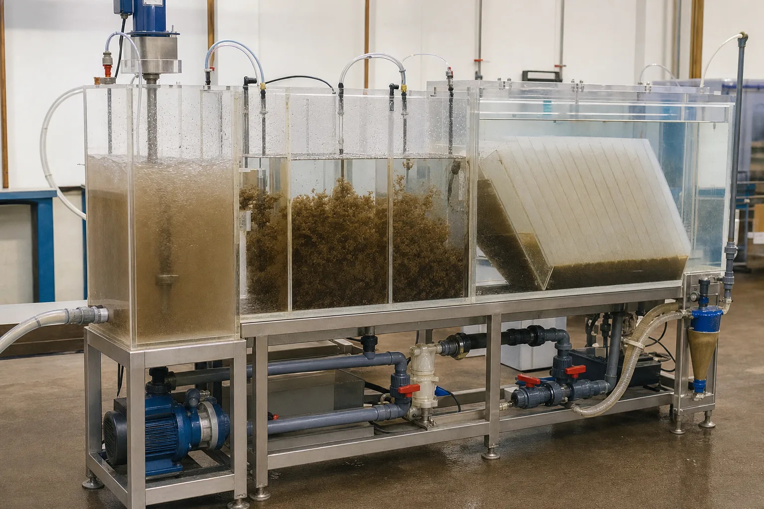 11Rapid mix/destabilization22Floc maturation and weighting33Lamella clarification44Underflow, cyclone, and recycle
What to identify
- 1Rapid mix/destabilization
- 2Floc maturation and weighting
- 3Lamella clarification
- 4Underflow, cyclone, and recycle
Figure takeaway
High-rate clarification is a controlled train, not a magic tank. Chemistry, collision growth, separation, and carrier circulation must finish within a short hydraulic residence time.
How to verify it in the field
Sample every compartment for turbidity, size, and settling velocity. Reconcile feed, chemical, polymer, carrier recovery, underflow solids, and effluent in a complete solids balance.
A same-footprint comparison shows more area, but floc quality still governs
The open basin on the left relies on its surface and a long path. The lamella basin on the right divides flow into short channels, while paired jars compare effluent.
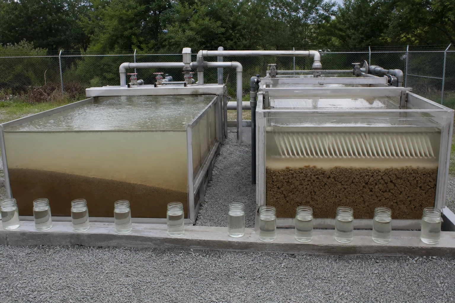 11Conventional surface/long path22Inclined short settling paths33Sludge blankets and underflow44Paired effluent samples
What to identify
- 1Conventional surface/long path
- 2Inclined short settling paths
- 3Sludge blankets and underflow
- 4Paired effluent samples
Figure takeaway
Plates add usable horizontal projected area and shorten travel to a collecting surface. They cannot make a stable colloid settle; compare systems under the same water, flow, and chemistry.
How to verify it in the field
Measure flow per projected area, feed/effluent TSS and turbidity, floc settling, blanket, and weir loading. Raise flow stepwise to locate the true effluent-break point.
Plates, cyclone, flow control, and sludge samples govern sustained capacity
Operators inspect deposits and wash access on the plate pack. Nearby cyclone valves control carrier recovery, while underflow and effluent samples expose fouling, media loss, or wasting problems.
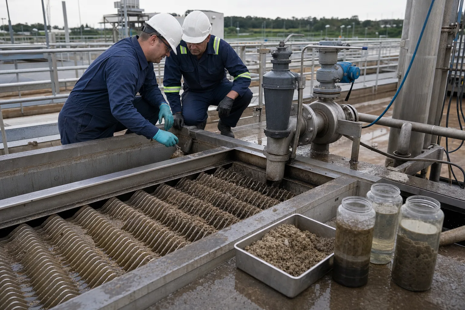 11Plate fouling and channels22Inspection/wash access33Underflow and sludge samples44Cyclone, valves, and flow meter
What to identify
- 1Plate fouling and channels
- 2Inspection/wash access
- 3Underflow and sludge samples
- 4Cyclone, valves, and flow meter
Figure takeaway
A clear short-term effluent does not prove health. Fouling removes area, worn cyclones lose sand, too little wasting raises the blanket, and too much wasting removes carrier and seed sludge.
How to verify it in the field
After isolation, inspect spacing, deposits, and deformation. In operation trend plate-zone head, cyclone pressures and split, media inventory, underflow concentration, return/waste flow, and wear parts.
Six steps from raw water to clear effluent and recovered carrier
Separate chemistry, hydraulics, and solids circulation to see where high rate is created or lost.
1 Rapid mix
Feed + coagulant → destabilized colloids
Disperse chemistry quickly and form microfloc.
2 Ballast/return
Microfloc + polymer + media/return sludge
Add seed area and weight for robust dense floc.
3 Maturation
Controlled mixing → floc growth
Provide collision, bridging, and structural stabilization.
4 Plate clarification
Dense floc ↓ | clear water ↑
Use projected area and short paths for high footprint loading.
5 Underflow classification
Carrier sludge → cyclone/thickening
Separate reusable carrier or active sludge from waste solids.
6 Recycle and waste
Carrier/seed returns; excess sludge leaves
Control media inventory, blanket, and total solids balance.
What the four subsystems must do
High-rate capacity is the combined result of four functions remaining online.
Coagulation and maturation
- Primary role
- Match pH/coagulant/polymer and form dense shear-resistant floc
- Typical failure
- Under/overdose, wrong sequence, low alkalinity, weak mixing, or floc breakup
- Key evidence
- Feed chemistry, dose, pH/alkalinity, G×t, particle size, settling rate, jar/pilot tests
Carrier/solids loop
- Primary role
- Supply and recover microsand, magnetite, or concentrated return sludge
- Typical failure
- Low inventory, poor cyclone split, dilute return, wear, or carrier lost in waste
- Key evidence
- Inventory, recovery, cyclone pressure, underflow solids, makeup and waste mass balance
Plates and water distribution
- Primary role
- Distribute rise flow and collect settling particles over projected area
- Typical failure
- Short circuit, local overload, fouled/deformed plates, bubbles, or uneven weirs
- Key evidence
- Flow, plate-zone head/rise rate, weir load, tracer, deposits, sectional effluent
Hopper, scraper, and wasting
- Primary role
- Concentrate and move settled solids; control blanket, recycle, and waste
- Typical failure
- Septic/floating solids, high blanket, stalled scraper, blocked line, or over-wasting
- Key evidence
- Blanket, torque, underflow TSS, return/waste flow, gas, pump pressure, sludge destination
Inclined settling and ballasted flocculation may be used separately or together. Do not transfer a surface loading, dose, or 'ten times faster' claim from one water and configuration to another; verify particle settling, projected area, reaction, inventory, and residuals handling together.
Align three data groups with each load change
Feed and reaction
Flow, temperature, turbidity/TSS, size, pH, alkalinity, dissolved/particulate targets, coagulant/polymer/media dose, and mix intensity/time by zone.
Clarification hydraulics
Calculate loading by footprint and projected area; trend plate-zone head, sectional effluent, weir load, turbidity/TSS/TP, and peak-flow response.
Solids and recovery
Floc settling, blanket, underflow solids, recycle/waste, cyclone pressure and carrier recovery; close daily carrier and total-solids balances.
How combined signals locate poor effluent
- Combined signal
- Small loose floc in reaction and fine solids uniformly across plate effluent
- Suspect first
- Wrong coagulation pH/dose, polymer sequence, short maturation, or low carrier inventory
- Next step
- Run dose gradients on current water, verify pumps and media balance, then restore chemistry/maturation before washing plates
- Combined signal
- Floc looks sound, but only some launders turn cloudy and plate-zone head or local velocity changes
- Suspect first
- Short circuit, uneven weir, plate fouling/deformation, or trapped bubbles taking projected area offline
- Next step
- Sectional sample and trace, level launders, isolate/wash modules, and find the abnormal inlet or gas source
- Combined signal
- Media makeup rises, underflow gets lighter, and cyclone underflow/overflow changes
- Suspect first
- Wrong cyclone pressure, worn nozzle/liner, or return-pump/valve fault causing poor recovery
- Next step
- Measure cyclone pressures and solids/size in both splits, inspect wear and piping, then close the carrier balance
- Combined signal
- Blanket rises, underflow is very dense or gassy, and scraper torque/pump pressure changes
- Suspect first
- Insufficient wasting, stalled scraper, blocked underflow, or septic deposits re-entraining
- Next step
- Confirm blanket/torque, clear and increase wasting gradually, and protect the carrier/seed inventory from one large purge
Four common misconceptions
High rate means simply moving water faster
It raises particle settling velocity and effective projected area first. With neither change, more flow only carries solids out.
Every plate clarifier is a sand-ballasted process
Plates, dense-sludge recycle, and microsand weighting are distinct mechanisms that may be separate or combined.
More, tighter plates are always better
Very tight spacing fouls more easily and can worsen flow. Angle, spacing, cleaning, distribution, and particle behavior must fit.
Clear effluent makes underflow and carrier irrelevant
Inventory errors accumulate before a sudden failure; media makeup, recycle, waste, and cyclone performance require long-term balance.