Illustrated guide · Equipment cutaway
How do a Roots blower and diffusers transfer oxygen into water?
Separate positive-displacement air delivery and system backpressure from fine-bubble formation, gas transfer, DO feedback and diffuser fault diagnosis.
Direct answer
Direct answer
A Roots blower does not make oxygen; it delivers air containing about 21% oxygen to the basin floor. Diffusers divide that air into bubbles, and oxygen crosses the gas–water interface under a concentration driving force. A Roots machine is a rotary positive-displacement blower. Timing gears keep two non-contacting lobed rotors counter-rotating, carrying nearly fixed-volume air pockets from inlet to discharge. It provides little gradual internal compression; each pocket equalizes with the higher-pressure discharge, so pressure is imposed mainly by water depth, diffuser headloss and piping/valve resistance. Speed chiefly sets volume flow. When resistance rises, flow may change modestly while power, discharge temperature, noise and mechanical load rise; never deadhead it, and protect it with filtration, check/relief, silencing and pressure/temperature limits. Fine bubbles usually improve interfacial area and residence time, but process-water surfactants, solids, salts and hydrodynamics reduce real transfer below clean-water ratings through alpha and other corrections. Fine-pore membranes foul, scale, harden or tear, changing headloss and distribution. Aeration must meet both oxygen and mixing duties: one DO setpoint does not prove there are no dead zones. Diagnose with synchronized mass/standard airflow, header pressure, blower power/temperature, zone flow/valves, diffuser dynamic wet pressure, DO/OUR and process load.
Four conditions turn air into useful dissolved oxygen
Blower flow and visible bubbles do not by themselves prove efficient oxygen delivery.
Operate the blower inside differential, temperature and speed limits
Inlet filter/silencer, clearances, lubrication, check and relief must work. Water depth plus fouled-diffuser backpressure must remain inside the OEM curve and VFD/cooling limits.
Distribute air inside each diffuser's operating window
Headers, laterals and valves/orifices must balance zones. Too little promotes maldistribution/fouling; too much raises loss, coarsens bubbles or strains membranes.
Provide interface, residence time and driving force
Small bubbles and submergence often increase KLa, but temperature, salinity, DO saturation, alpha, surfactants and mixing control real transfer.
Follow oxygen load without losing minimum mixing
DO control can vary air, but probe location/fouling and lag can mislead. Low-load turndown must still prevent solids deposition, dead zones and prolonged underflow at diffusers.
The blower room links filtered air, low-pressure machines, a common header and basin grids
Multiple blowers draw through inlet filter/silencers and feed a large air header; outside, laterals serve basin grids. Plants may use Roots, screw or centrifugal technology, so casing shape alone does not identify it.
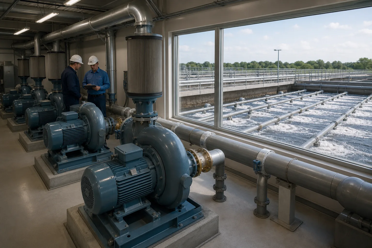 11Inlet filter / silencer22Motor and low-pressure blower package33Check/relief and common air header44Basin zone laterals / grids
What to identify
- 1Inlet filter / silencer
- 2Motor and low-pressure blower package
- 3Check/relief and common air header
- 4Basin zone laterals / grids
What this proves
The blower must overcome the entire pressure chain. Selection uses limiting water level, clean/fouled diffuser loss, piping loss and required mass airflow, plus parallel/VFD operating strategy—not basin size alone.
Field check
Verify nameplate and technology; trend inlet temperature/pressure/filter drop, discharge pressure/temperature, actual airflow, speed and power. Check each zone pressure/flow/DO and duty/standby changes.
The Roots cutaway shows timing gears holding non-contacting lobes in phase
The motor drives the shafts; timing gears synchronize three-lobe rotors. Small rotor-to-rotor and rotor-to-casing clearances let trapped pockets travel from inlet to outlet.
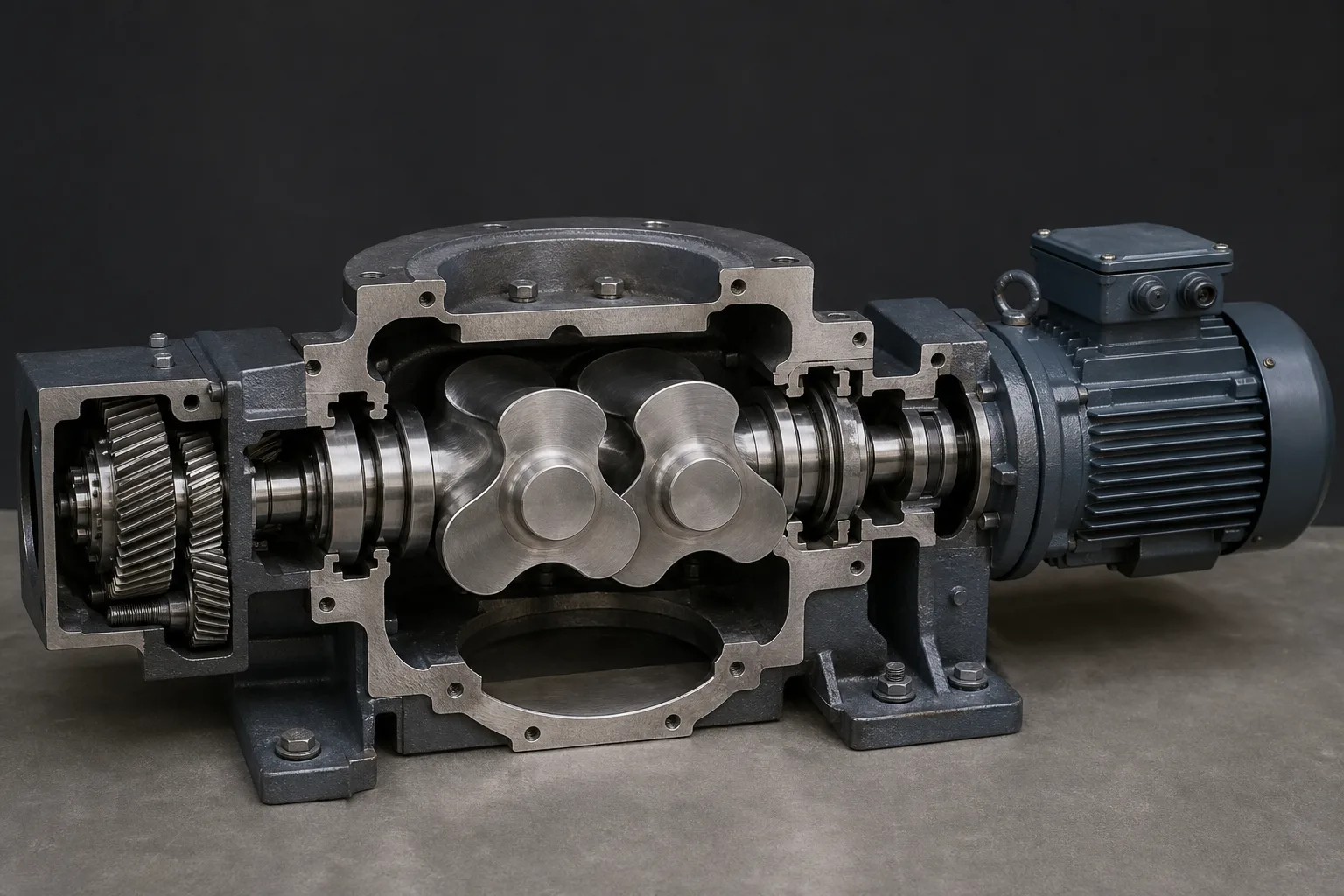 11Timing gears and phase22Twin three-lobe rotors / clearances33Inlet–trapped pocket–outlet path44Motor, bearings and seals
What to identify
- 1Timing gears and phase
- 2Twin three-lobe rotors / clearances
- 3Inlet–trapped pocket–outlet path
- 4Motor, bearings and seals
What this proves
A Roots machine transports pockets rather than gradually compressing between lobes. Equalization at discharge creates pulsation, noise and heat. Large clearances increase slip; small clearances risk rub after thermal growth or debris.
Field check
Follow OEM checks for rotation, backlash, end/radial clearance, vibration, temperature, oil, seals and deposits. Hand-turn unloaded, start with required unloading/bypass, and never start against a closed valve.
A transparent rig puts blower flow, header pressure, bubble plumes and DO in one test
A Roots package supplies a monitored manifold; five disc diffusers create plumes while pressure, flow, temperature and DO instruments connect air input to water response.
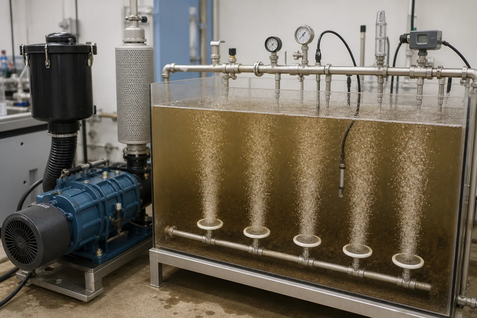 11Roots blower and inlet conditioning22Header pressure/flow and zone valves33Disc diffusers and bubble plumes44DO/temperature probe and response
What to identify
- 1Roots blower and inlet conditioning
- 2Header pressure/flow and zone valves
- 3Disc diffusers and bubble plumes
- 4DO/temperature probe and response
What this proves
Airflow is input and DO is water-phase result. Between them lie diffuser loss, bubble size, depth, KLa, alpha and biological oxygen uptake. Header pressure alone or one DO probe misses the chain.
Field check
At steady state, step one zone's flow and log standard/mass air, zone pressure, temperature, power, plumes and multiple DO points. Treat clean-water tests as a baseline, not direct process performance.
Four tanks contrast clean fine pores, coarse bubbles, fouling and membrane rupture
A clean membrane makes uniform fine bubbles; coarse openings/high flow make fast large bubbles; fouling causes patchy low flow and high loss; a tear creates a concentrated coarse jet.
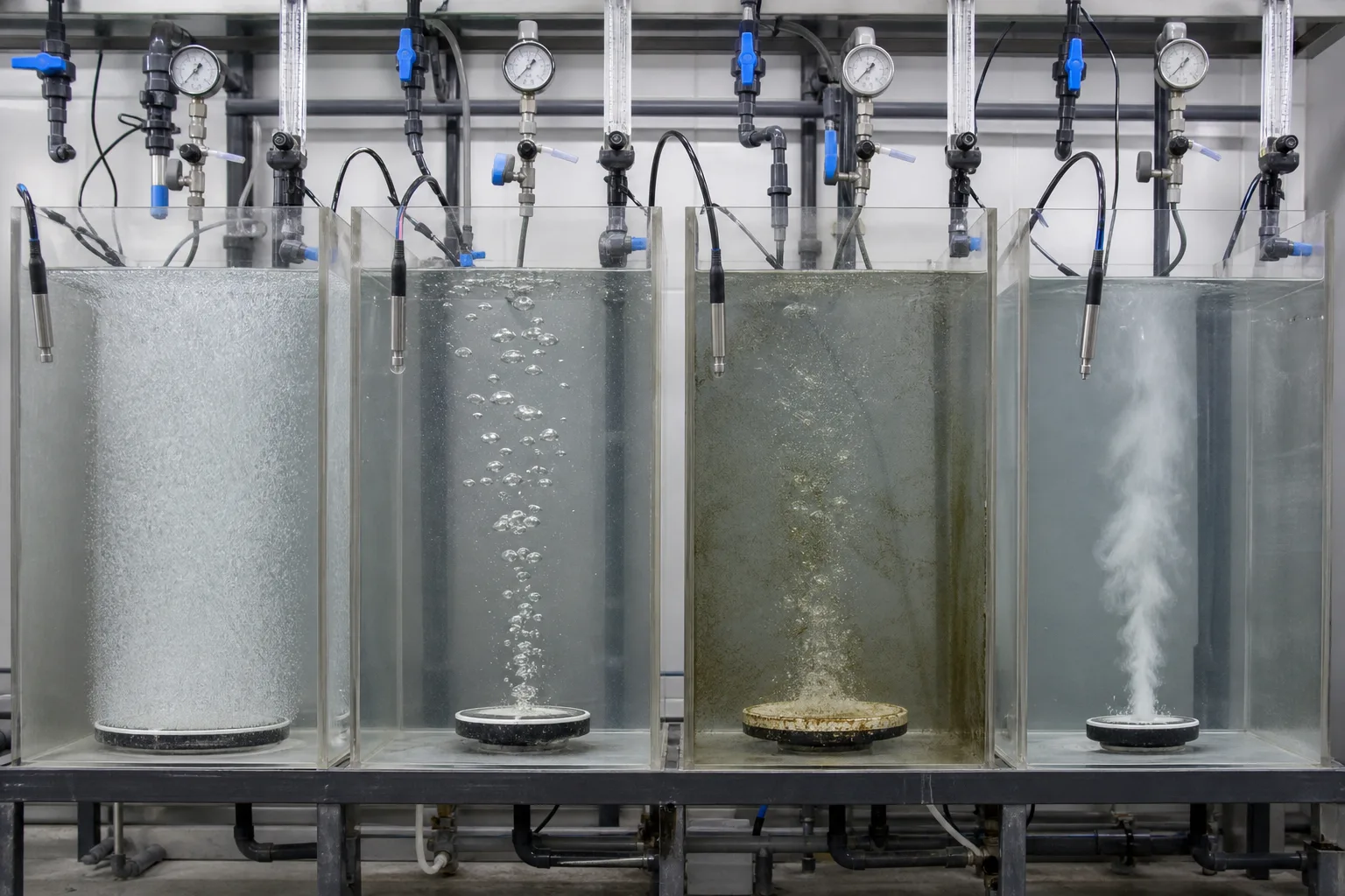 11Clean fine pore: uniform bubbles22Coarse/high-flow: fast large bubbles33Fouled membrane: patchy, high loss44Torn/detached membrane: coarse jet
What to identify
- 1Clean fine pore: uniform bubbles
- 2Coarse/high-flow: fast large bubbles
- 3Fouled membrane: patchy, high loss
- 4Torn/detached membrane: coarse jet
What this proves
Appearance localizes faults but does not quantify transfer. Fine bubbles generally improve area/residence; coarse bubbles mix strongly at lower resistance. Fouling often raises pressure at the same flow, while rupture may lower local loss but reduce oxygen efficiency.
Field check
At equal depth/temperature compare branch flow and pressure, bubble coverage, DO gradients and oxygen effect per air/energy. Clean or replace only by OEM procedures—do not improvise acid treatment or puncture membranes.
Rotor clearances, gears/bearings and diffuser membranes jointly determine useful aeration
Technicians inspect Roots rotors, timing gears and bearings while clean, scaled and torn diffuser parts show simultaneous aging at the air source and basin endpoint.
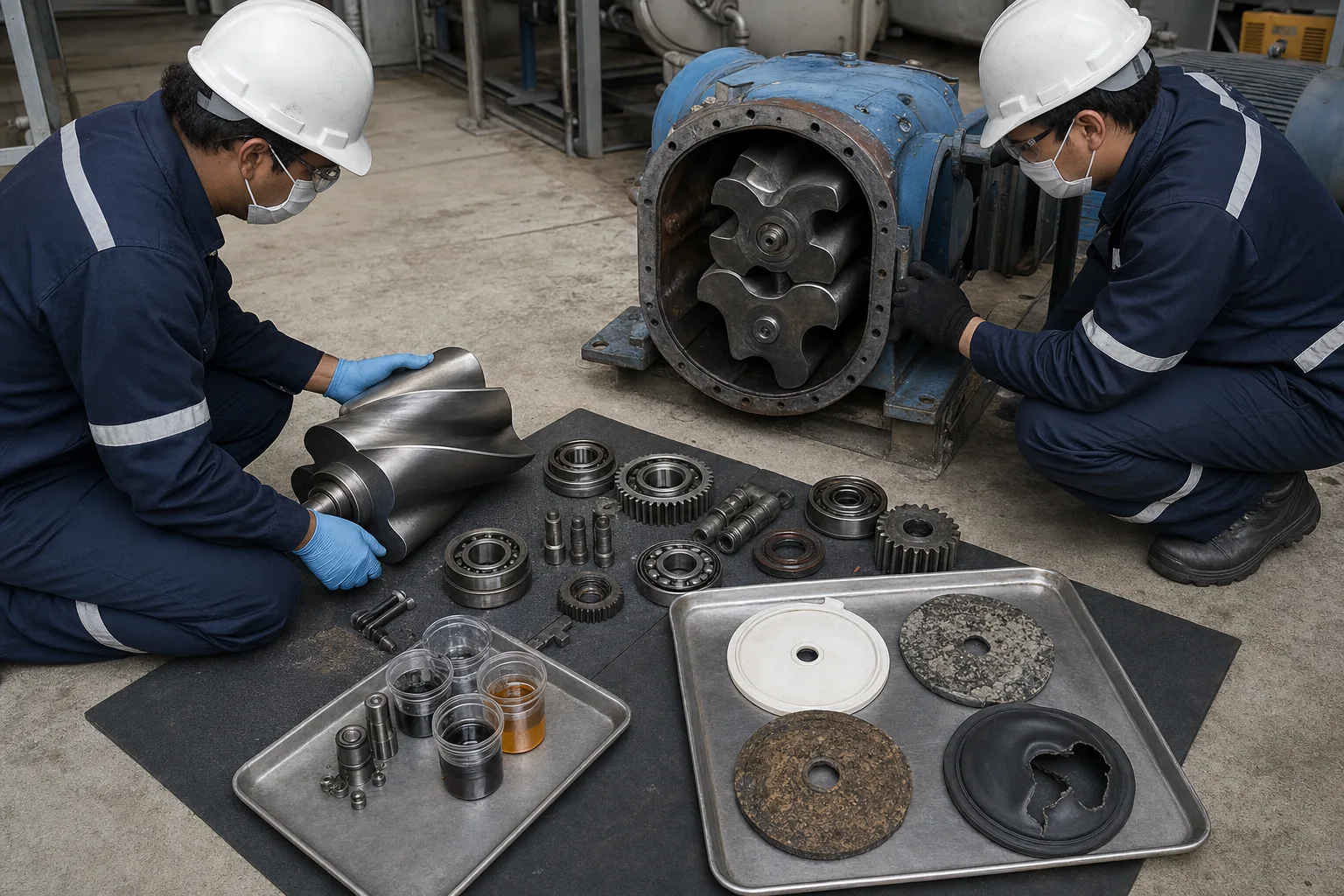 11Roots rotor surfaces and clearance22Timing gears, bearings and lubrication33Scaled/biofouled diffuser disc44Torn/hardened membrane and check
What to identify
- 1Roots rotor surfaces and clearance
- 2Timing gears, bearings and lubrication
- 3Scaled/biofouled diffuser disc
- 4Torn/hardened membrane and check
What this proves
Blower degradation and diffuser fouling can coexist: one raises slip/friction/vibration, the other raises system backpressure. Increasing speed to hold DO can hide both while increasing energy and temperature.
Field check
Align blower curve and P–Q–power trend with zone headloss, plumes and DO/OUR. Measure clearances, gears/bearings, oil/seals, and diffuser before/after cleaning loss; isolate against basin backflow.
Six energy and mass steps from ambient air to respiration
Delivery, distribution, bubble formation and dissolution are continuous but distinct processes.
1 Intake
Ambient → filter/silencer → blower
Provide clean low-loss air and measure state for mass/standard conversion.
2 Displace
Rotor pockets → discharge
Speed sets volume; backpressure sets differential, power and temperature.
3 Protect/header
Check/relief/silencer → common header
Prevent reverse flow, overpressure and excessive pulsation/noise.
4 Zone
Header → valve/orifice/meter → basin lateral
Match oxygen demand and minimum mixing by grid.
5 Bubble/transfer
Membrane pore → bubble → interface → liquid
Create KLa from area, residence and concentration driving force.
6 Consume/control
Dissolved O₂ → demand → DO/OUR feedback
Track load while verifying mixing, ammonia and effluent response.
Verify four layers separately
Mechanical air delivery, network pressure, transfer and biological use have different evidence.
Blower/drive
- Normal role
- Deliver required mass air inside differential/speed limits
- Failure
- Filter, slip/rub, gear/bearing/lube, overtemp/pressure or VFD boundary
- Evidence
- Inlet/discharge P/T, flow, speed, power, vibration, oil, filter drop and trips
Header/zones
- Normal role
- Distribute air at low loss with control and backflow protection
- Failure
- Imbalance, leaks/condensate, failed check/relief, parallel interaction
- Evidence
- Header/zone P/Q, valves, drains, leaks, parallel curves and water level
Diffuser/bubbles
- Normal role
- Create uniform bubbles within flow and pressure window
- Failure
- Mineral/bio/air-side fouling, hardening/tear, maldistribution
- Evidence
- Dynamic wet pressure, plume/coverage, branch flow, pre/post clean loss and membrane
Liquid/process
- Normal role
- Transfer and use O₂ while mixing solids
- Failure
- Low alpha, load spike, probe bias, dead zones or overaeration
- Evidence
- Calibrated multi-point DO, OUR, NH₄/COD, MLSS, temperature, mixing and oxygen/energy
Clean-water SOTE/SAE and process oxygen transfer are not interchangeable. Correct for temperature, pressure/altitude, salinity, DO, alpha/beta, depth and fouling; determine project values through design and accepted oxygen-transfer testing.
Synchronize three groups across a load cycle
Air and energy
Inlet/discharge absolute P/T, mass/standard flow, speed/valves, power, vibration, filter drop, relief events and running units.
Network and diffusers
Header/zone P/Q, level, dynamic wet pressure, plume coverage, condensate, valves, cleaning/replacement and pre/post loss.
Oxygen and process
Calibrated multi-point DO, OUR/SOUR, temperature, load, NH₄/COD, MLSS and mixing; compare oxygen result per air and energy.
Diagnose with pressure, flow, power and DO together
- Signal
- At the same flow, header pressure and power rise over months while local plumes shrink
- First suspicion
- Diffuser fouling, condensate/valve restriction or inlet filter loading
- Next action
- Separate inlet drop from discharge/zone loss; map flow/wet pressure/plumes and clean by OEM rather than adding speed
- Signal
- Header pressure falls suddenly and one zone develops a coarse jet with worse DO efficiency
- First suspicion
- Torn/detached membrane or major lateral/connection leak
- Next action
- Isolate the grid, compare P/Q/DO, inspect membrane/check/fittings during outage and rebalance
- Signal
- Airflow and plumes are normal but DO falls while NH₄ or OUR rises
- First suspicion
- Load/oxygen uptake, temperature or alpha shift before equipment failure
- Next action
- Verify probes and load/OUR, raise zone air within limits, inspect mixing/recycle and use process response
- Signal
- Flow falls while discharge temperature/vibration or rubbing noise rises
- First suspicion
- Inlet blockage, timing/bearing/lube/clearance fault or excessive differential
- Next action
- Unload/stop and swap standby per protection; inspect filter, pressure, oil, vibration and hand rotation—do not accelerate
Four common mistakes
Roots lobes progressively squeeze air internally
They mostly carry fixed pockets and equalize at discharge; screw and centrifugal mechanisms differ.
More/larger bubbles mean more oxygen
Transfer depends on area, residence, driving force and alpha; large bubbles may mix well but transfer less per air.
One acceptable DO proves uniform aeration
A point can hide dead zones, local excess, probe fouling and inadequate mixing.
Raise blower speed whenever pressure rises
Rising pressure may be blockage; blind speed increases energy, heat and damage risk.