Illustrated guide · Equipment cutaway
How does a desalination energy-recovery device work?
Start with the pressure retained in SWRO brine, then follow the four streams, ceramic-rotor liquid piston, main and booster pump duties, flow balance, mixing and pressure-loss diagnosis.
Direct answer
Direct answer
Seawater RO raises feed above osmotic pressure. Only part permeates as low-pressure product; the concentrate still leaves the membrane array with most of its pressure. Throttling that brine wastes hydraulic power. An isobaric pressure exchanger does not desalinate and usually does not first generate electricity. It directly transfers pressure from high-pressure brine to low-pressure pretreated seawater through rotating ducts that act as liquid pistons. A ceramic rotor contains axial channels and spins between high- and low-pressure port plates. On the low-pressure side, fresh seawater fills a duct and expels depressurized brine. After rotation to the high-pressure side, HP brine enters from the other end and pushes the seawater out at nearly brine pressure. The short liquid interface, precise port timing and flow balance limit mixing; seawater in micron clearances forms a fluid bearing. PX flow is roughly concentrate flow, while the main HP pump pressurizes roughly the permeate-equivalent share of feed—actual design includes leakage, mixing and margins. A small booster then makes up PX, piping and membrane-array pressure losses before the two HP seawater streams combine. Real savings depend on four-port P/Q balance, pressure drop, leakage/mixing, booster and main-pump efficiency—not device nameplate efficiency alone. Prevent air/cavitation, particles, dry running, operation outside pressure/flow/temperature limits and opening before full depressurization.
Four conditions return brine pressure to the feed
Available brine energy is only the start; four streams, two pumps and pressure boundaries must balance.
Balance HP brine and PX seawater flows
Imbalance shifts the liquid interface, increasing brine-to-feed mixing or fresh-water loss with depressurized brine. Use OEM HP/LP windows and intended leakage direction, not an assumed perfect equality.
Assign the correct head to each pump
The main pump directly pressurizes its feed share; the PX pressurizes another share; the booster only covers PX/array loss. Excess throttling or pumps away from best efficiency consume the recovered benefit.
Keep all four ports flooded, clean and non-cavitating
Particles, scale, biofilm, entrained air or low inlet pressure damage fluid bearings, obstruct ducts and cause noise. Flush and vent before start, meet inlet pressure/water-quality limits and never run dry.
Accept on system SEC, not one efficiency
Divide all main, booster, intake/pretreatment and auxiliary energy by compliant permeate and normalize salinity, temperature, recovery and output. Pressure-transfer efficiency is not plant savings.
A large SWRO train uses a parallel pressure-exchanger array for brine-scale flow
Multiple devices connect between HP and LP headers; a smaller pump restores pressure loss and gauges monitor branches. Modular parallel units scale capacity and redundancy.
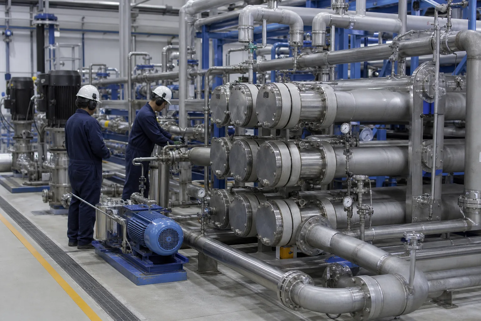 11Parallel isobaric PX array22Four HP/LP process headers33Circulation / booster pump44Pressure, valves and sample branches
What to identify
- 1Parallel isobaric PX array
- 2Four HP/LP process headers
- 3Circulation / booster pump
- 4Pressure, valves and sample branches
What this proves
The PX array does not eliminate every HP pump. It reduces main-pump flow from total feed toward the permeate-equivalent share, while the PX path handles concentrate-scale flow; recovery and balance set the exact split.
Field check
Use the P&ID to identify HP brine in, LP brine out, LP seawater in and HP seawater out—never infer from pipe position. Log header P/Q/T/conductivity, pump power and branch balance.
The cutaway shows axial rotor ducts, port plates, sleeve clearance and four process ports
A multi-duct rotor spins inside a stationary sleeve. End assemblies connect ducts alternately to HP and LP ports; exposed shaft, materials and port layout vary by supplier/model.
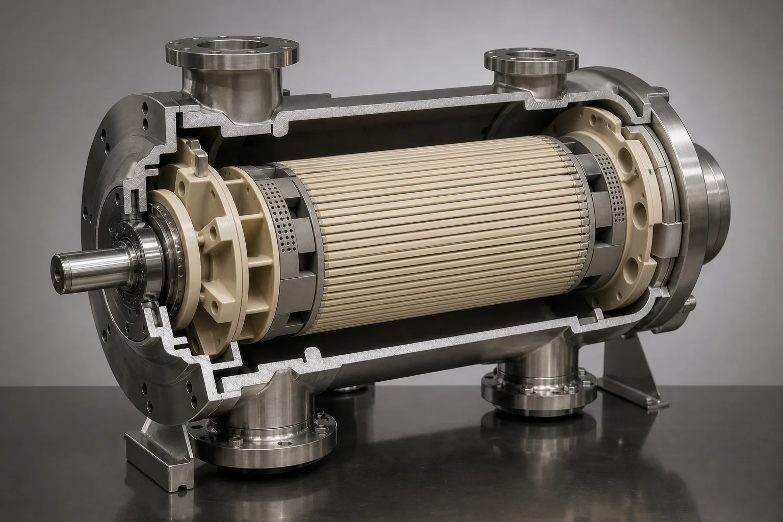 11Axial ducts / ceramic rotor22HP/LP port plates and timing33Sleeve clearance / seawater bearing44Pressure housing and four ports
What to identify
- 1Axial ducts / ceramic rotor
- 2HP/LP port plates and timing
- 3Sleeve clearance / seawater bearing
- 4Pressure housing and four ports
What this proves
Pressure crosses through a liquid column, not the solid rotor wall. HP brine drives seawater in the same duct; port plates isolate ducts at pressure boundaries and clearances both lubricate and leak slightly.
Field check
Confirm materials and limits from the OEM cutaway. Trend four-port drop and abnormal sound/speed/vibration where instrumented. Fully depressurize and protect ceramic parts from impact during service.
A transparent rig combines two fluids, four pressures and the booster circuit
Blue/red are teaching conventions only; actual HP sides require instruments and flow arrows. The rotor exchanges pressure and the bottom pump restores loop loss.
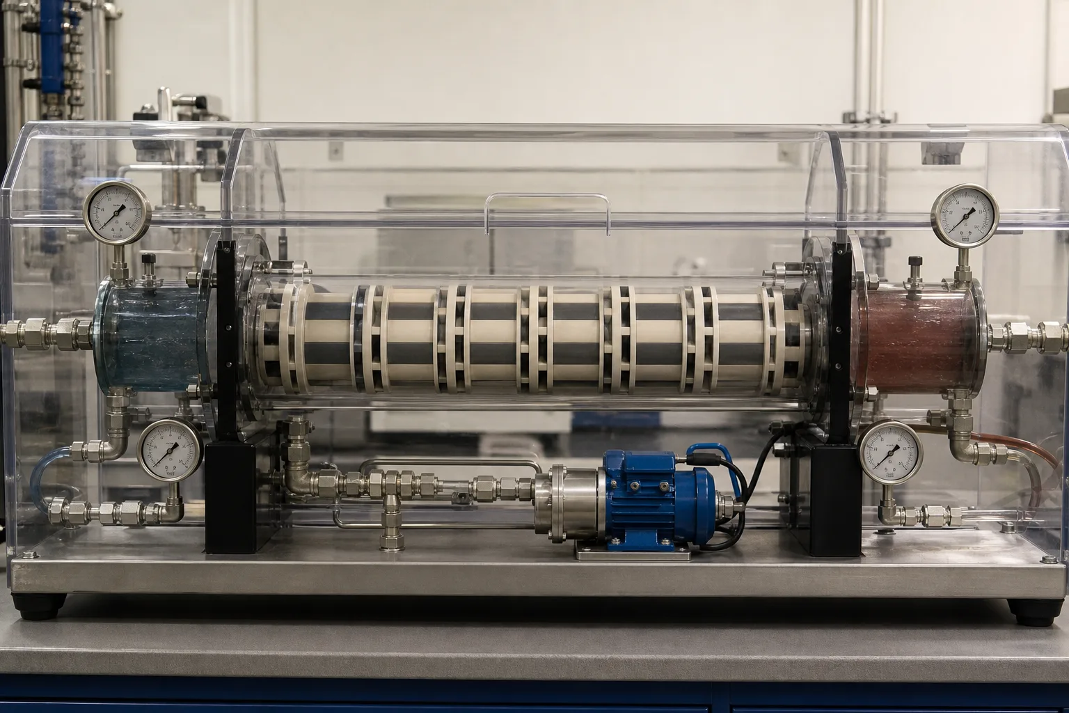 11LP inlet/outlet pressure pair22Rotating ducts and liquid interface33HP inlet/outlet pressure pair44Booster pump and flow control
What to identify
- 1LP inlet/outlet pressure pair
- 2Rotating ducts and liquid interface
- 3HP inlet/outlet pressure pair
- 4Booster pump and flow control
What this proves
Exchange is nearly isobaric, but HP seawater outlet is below HP brine inlet by device loss. The booster must cover that plus array/piping loss. Four pressures separate PX loss from pump and valve loss.
Field check
At steady output measure all four P/Q/T/conductivities together. Balance flow and estimate mixing; verify the booster develops necessary loss only rather than working against a throttled valve.
Three parallel SWRO trains show that ERD, pumps, membranes and control form one system
Each train contains controls, an HP pump, pressure vessels, PX/booster loop and instrumentation. Trains can stage with demand, but flushing, start and pressure ramp must coordinate.
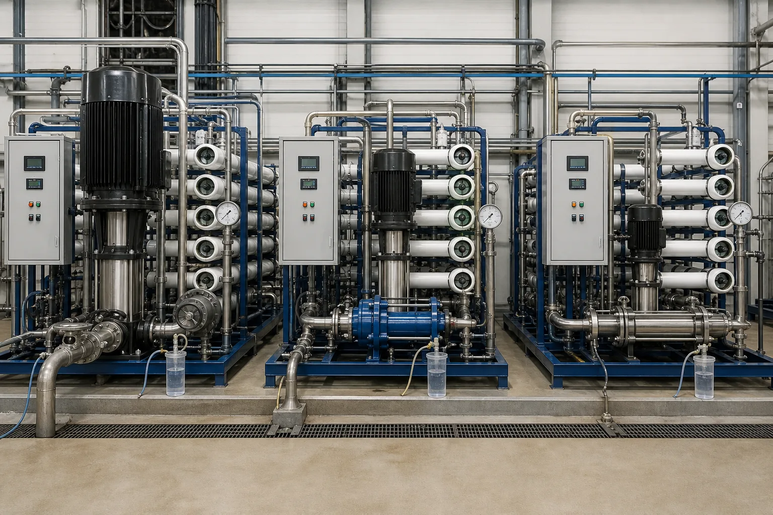 11Main HP pump and VFD/control22RO vessels and HP feed33ERD / booster loop44Permeate/brine sampling and instruments
What to identify
- 1Main HP pump and VFD/control
- 2RO vessels and HP feed
- 3ERD / booster loop
- 4Permeate/brine sampling and instruments
What this proves
ERD is one energy link. Membrane fouling, pretreatment loss, recovery changes and temperature/salinity alter PX point and SEC. Rising energy is not automatically an ERD fault.
Field check
Per train log feed/permeate/brine Q, membrane P and conductivity, main/booster and auxiliary kW. Compare normalized kWh/m³ at like temperature, salinity and recovery.
Teardown aligns ceramic rotor, end-port surfaces, seals and particle evidence
Technicians inspect a ducted ceramic rotor and end flow paths; seal rings, captured deposits and four-port water samples distinguish particles, scale, corrosion or imbalance.
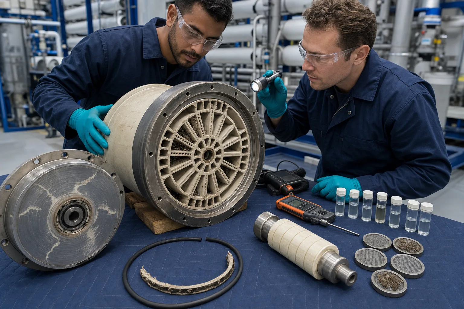 11Ducted ceramic rotor22End cover / port-plate surface33Seal, sleeve and clearance parts44Captured deposits and port samples
What to identify
- 1Ducted ceramic rotor
- 2End cover / port-plate surface
- 3Seal, sleeve and clearance parts
- 4Captured deposits and port samples
What this proves
Many PX symptoms originate upstream or in operation rather than rotor wear. Particles, gas, deposits and pressure shock disturb it; imbalance often appears first as HP-feed conductivity and LP-discharge composition changes.
Field check
Diagnose online P/Q/conductivity, sound and filter drop before OEM flush/stop. Isolate, depressurize and LOTO before opening; document ceramic/port/seal/deposit condition and never grind or strike parts without authorization.
Eight steps return RO brine pressure to feed
Close water, salt, pressure and electric-power balances together.
1 Split feed
LP pretreated seawater → main-pump and PX branches
Provide flooded, clean and metered feed to both paths.
2 Main pump
Permeate-scale branch → HP pump → RO header
Electrically pressurize one share and control total membrane pressure.
3 Membrane
HP feed → LP permeate + HP brine
Make freshwater while preserving brine pressure for recovery.
4 HP exchange
HP brine → duct → expels HP seawater
Direct liquid-to-liquid pressure transfer with limited loss/mixing.
5 LP refill
LP seawater → duct → expels LP brine
Reload fresh feed and discharge depressurized concentrate.
6 Boost/combine
PX HP seawater → booster → main HP stream
Restore loss and meet membrane feed flow/head.
7 Route products
LP brine → outfall/use; permeate → post-treatment
Close salt/water paths—pressure recovery is not salt recovery.
8 Verify SEC
All pump/aux kW ÷ compliant permeate m³/h
Prove train savings on a consistent boundary.
Four subsystems have distinct pressure and separation duties
HP pump, PX, booster and membrane cannot substitute for one another.
RO array
- Normal duty
- Split HP feed into LP low-salt permeate and HP brine
- Typical mismatch
- Fouling/scale, recovery/temp/salinity shift, membrane/seal leak
- Evidence
- feed/brine/permeate P/Q/EC, normalized flow/pass, stage DP/recovery
Main HP pump
- Normal duty
- Provide electric pressure to its feed share
- Typical mismatch
- Off-BEP, VFD/valve loss, cavitation/wear or mismatch to PX flow
- Evidence
- suction/discharge P/Q, rpm, kW/efficiency, vibration/temp, valve
Pressure exchanger
- Normal duty
- Direct isobaric transfer between HP/LP brine/seawater
- Typical mismatch
- imbalance, mixing/leakage, high loss, gas/particles, obstruction/rotor issue
- Evidence
- four-port P/Q/T/EC, sound, branches, filter drop and flush response
Booster/circulation
- Normal duty
- Restore PX/array loss and deliver stable HP seawater
- Typical mismatch
- insufficient/excess head, throttling, cavitation, maldistribution or check failure
- Evidence
- pump P/Q/kW/efficiency, valve, membrane feed pressure and train flows
Hydraulic power scale is P≈Δp·Q, but OEM device efficiency definitions include pressure loss, leakage and mixing. Main-pump flow≈permeate and PX flow≈concentrate are conceptual; final design needs OEM tools/curves plus complete water and salt balances.
Retain three synchronized evidence groups
Four streams and balances
P/Q/T/conductivity at HP-brine in, LP-brine out, LP-seawater in and HP-seawater out, plus RO feed/permeate/brine; estimate mixing, leakage and branch maldistribution.
Pumps, valves and energy
Main/booster suction/discharge, rpm, kW/efficiency, valves/bypass, filter drop, per-train output and all auxiliaries for comparable SEC.
Reliability and condition
Sound/vibration/temp, start/flush/vent records, alarms/trips, upstream SDI/turbidity/particles, scale/bio trends and ceramic/seal observations.
Diagnose with four-port P–Q–EC and two-pump power
- Signal
- HP seawater conductivity rises while pressure transfer stays normal
- Suspect first
- Flow imbalance shifts interface toward brine-to-feed mixing, or leakage/port wear
- Next step
- Validate all flow meters/samples, adjust OEM flow ratio, align HP/LP EC and temperature before internal diagnosis
- Signal
- HP brine-in to HP seawater-out loss and booster power rise
- Suspect first
- PX/header/filter restriction, unequal branches, scale/particles or pressure-instrument error
- Next step
- Segment pressure loss and branch P/Q, check pretreatment/filter/flush; do not mask by permanently raising pump head
- Signal
- Gravel-like noise, vibration or unstable flow with low/gassy inlet
- Suspect first
- Entrained air, cavitation, incomplete flooding/venting or LP inlet restriction
- Next step
- Unload/stop by OEM logic; check level, venting, filters/valves and minimum inlet pressure—never run dry
- Signal
- Four-port performance looks normal but train SEC and membrane feed pressure rise
- Suspect first
- Membrane fouling/temp/salinity, pump efficiency, throttling or pretreatment auxiliaries
- Next step
- Combine normalized membrane data, both pump efficiencies and itemized kW to locate the new largest loss
Four common misconceptions
The ERD turns brine back into freshwater
It recovers pressure only; salt leaves in LP brine and permeate still comes from RO membranes.
A pressure exchanger generates power first
Isobaric ERDs transfer liquid pressure directly; Pelton/turbocharger paths are different technologies.
A 98% device makes the whole plant 98% more efficient
Device efficiency, savings versus no ERD and plant SEC are different metrics with other losses.
Similar four-port pressures prove good operation
Also verify flow ratio, conductivity mixing, leakage, loss, sound and pump power.