Illustrated guide · Equipment cutaway
What is actually inside an RO pressure vessel?
Follow the real feed, permeate and load paths through the FRP shell, spiral-wound elements, interconnectors, brine seals, end closures and thrust hardware.
Direct answer
Direct answer
The RO pressure vessel does not desalinate water; it is the FRP pressure boundary that houses and aligns the membrane elements. Pressurized feed enters the feed spacer and travels axially through a series of spiral-wound elements. Part permeates the membrane, spirals through the permeate carrier into each center tube, and joins the vessel permeate outlet through interconnectors and O-rings. Concentrate continues downstream. A brine seal blocks bypass between the element outside diameter and vessel bore. End adapters join the outer element center tube to the permeate port. A downstream thrust ring or specified load-bearing device transfers axial hydraulic load from the element train into the vessel, while shims or loading devices remove axial play. The end closure combines a head, seals, segmented retaining ring and ports; its exact arrangement is model-specific. Plants often use several elements in series, but element count, brine-seal direction, port orientation, thrust hardware and loading clearance must follow the membrane and vessel OEM manuals. Before opening a closure: stop, isolate, lock out, depressurize, prove zero pressure, drain and flush. A vessel head is never an ordinary fitting that may be loosened under pressure.
Four boundaries must be correct at the same time
Separation, pressure safety and maintainability depend on different parts, so every symptom is not simply a bad membrane.
An intact, correctly supported pressure boundary
Shell, end grooves, head seals, ports and saddles must be free of prohibited scratches, cracks, chemical attack and movement; never drill, sand or alter supports outside OEM rules.
A continuously sealed permeate-tube train
Interconnectors, end adapters and O-rings connect center tubes while excluding feed/concentrate. Misalignment, cuts, missing seals or contamination can raise product conductivity abruptly.
Controlled bypass and axial movement
The brine seal blocks shell-side bypass; the specified thrust device carries axial load; shims/loading hardware remove play that otherwise amplifies start-stop shock and telescoping.
Traceable orientation, position and hardware
Record every element position, flow direction, brine-seal orientation, connector, shim and closure part so pressure drop, fouling and salt passage can be tied to a real location.
Field loading separates the spiral-wound element from the FRP pressure shell
Technicians align an element cart with the vessel axis. The open end exposes the closure location, while side and upper piping connect the feed, concentrate and permeate circuits.
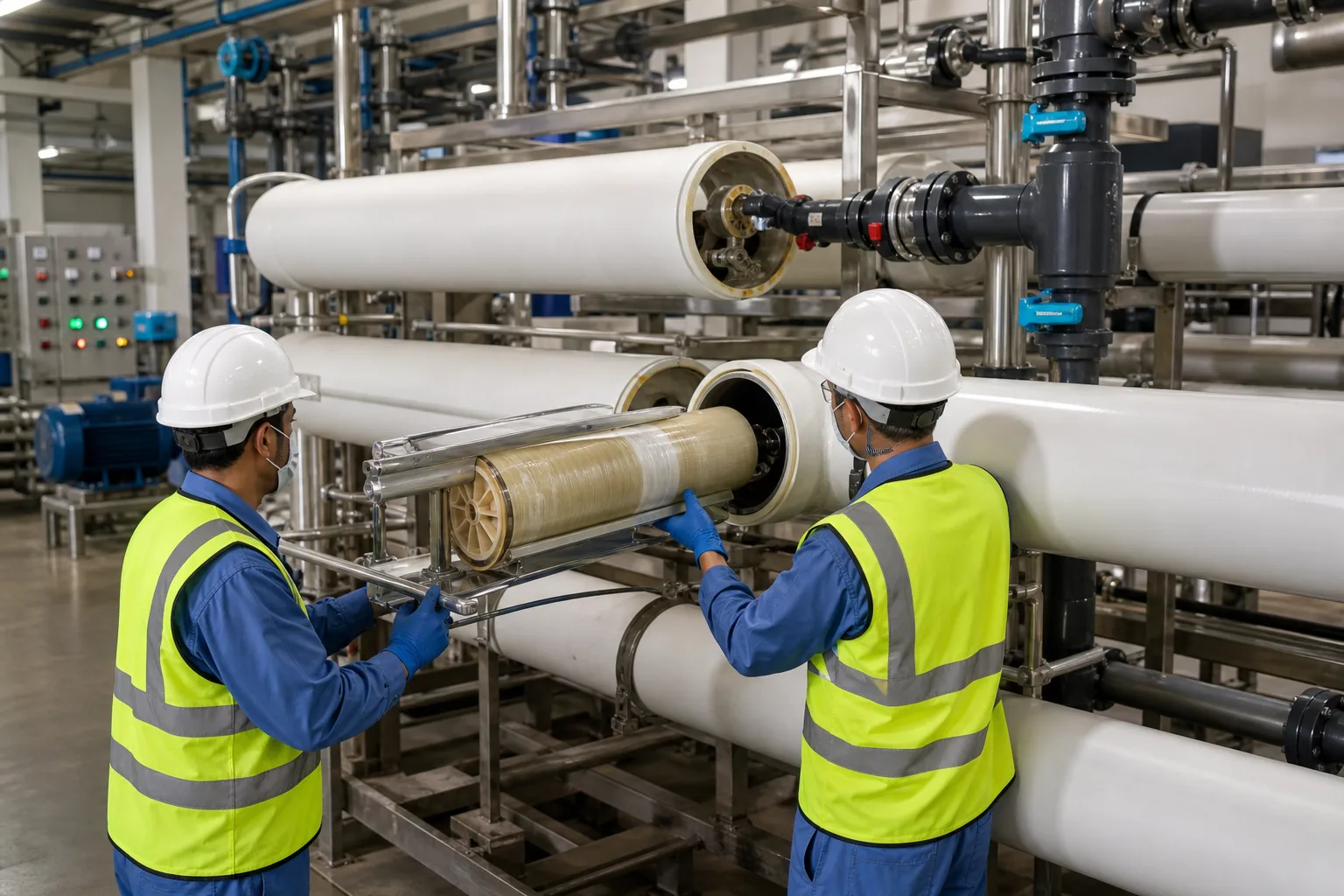 11FRP pressure shell22Spiral-wound element and loading cart33Open closure / end-adapter location44High-pressure feed/concentrate piping
What to identify
- 1FRP pressure shell
- 2Spiral-wound element and loading cart
- 3Open closure / end-adapter location
- 4High-pressure feed/concentrate piping
What this proves
The vessel contains pressure and locates the train; the element performs selective separation. Dry or pinched O-rings, sharp tools and off-axis pushing can create a conductivity or external-leak problem despite an apparently completed load.
Field check
Verify vessel model, rating, flow arrow, ports and supports. Clean the bore, use only approved seal lubricant, inspect wrapper and brine seal, use non-damaging tools, and log serial number, position and orientation.
The cutaway aligns serial elements, permeate interconnectors and both closures
Multiple spiral elements sit end-to-end; white interconnectors continue the permeate tube, and end assemblies close the high-pressure chamber and connect external piping.
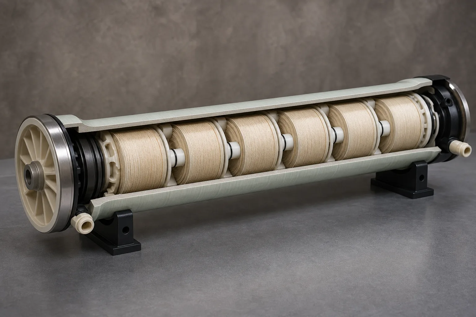 11FRP pressure cylinder22Series spiral-wound element train33Permeate interconnector and O-rings44Closures, ports and thrust end
What to identify
- 1FRP pressure cylinder
- 2Series spiral-wound element train
- 3Permeate interconnector and O-rings
- 4Closures, ports and thrust end
What this proves
The same concentrate stream feeds successive elements, so downstream salinity and osmotic pressure normally rise. Permeate remains inside the center-tube train; one failed O-ring can mimic sudden membrane salt rejection loss.
Field check
Match the assembly drawing for element count, connector, adapter, thrust ring and shims. Measure and remove excess axial play within OEM limits; do not use the head as an improvised element clamp.
A disciplined teardown exposes every closure, permeate and sealing component
Position-numbered elements are laid beside the head, segmented ring, end adapter, interconnectors, O-rings, brine seals and shims for inspection and controlled reassembly.
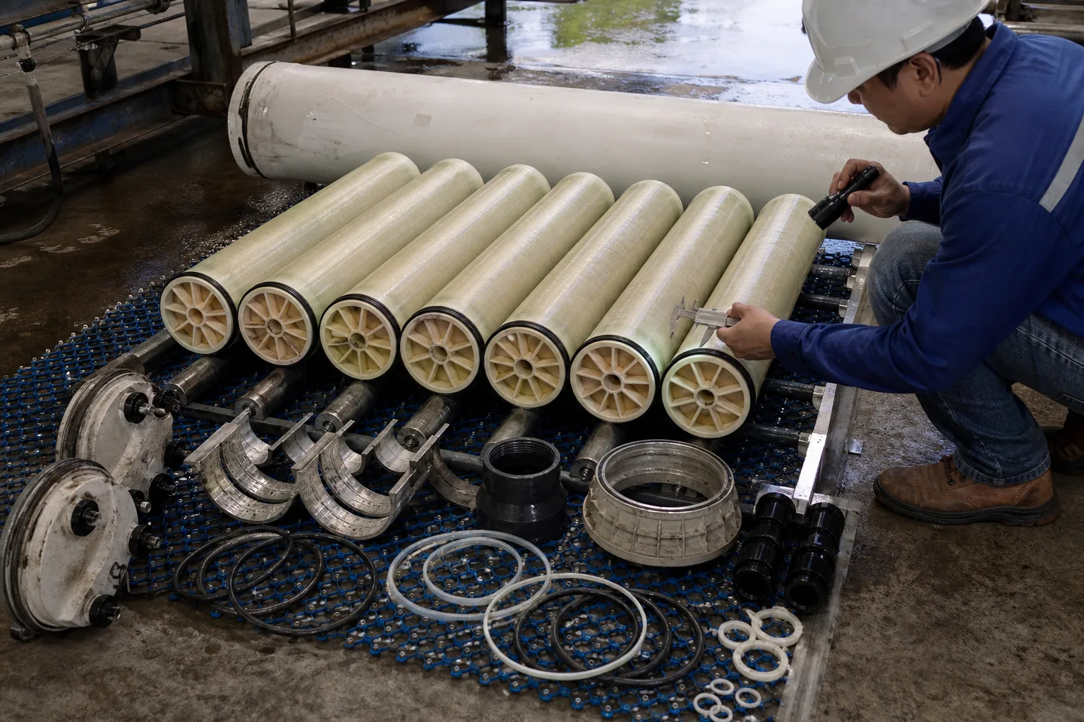 11Position-numbered element train22Head and segmented retaining ring33Permeate connectors and end adapter44O-rings, brine seal and shims
What to identify
- 1Position-numbered element train
- 2Head and segmented retaining ring
- 3Permeate connectors and end adapter
- 4O-rings, brine seal and shims
What this proves
The closure is a seal-and-load chain: the retaining ring locks the head, the head seal contains pressure, permeate O-rings isolate product water, and specified thrust parts carry axial load. Omitting one part creates a distinct hazard.
Field check
After verified depressurization, follow the OEM sequence and inventory every part. Inspect groove/ring seating, ports, seal cuts and flattening, connector scratches, brine-seal lip, thrust ring and shim thickness; do not reuse damaged pieces.
A transparent vessel separates shell-side feed, center-tube permeate and end piping
Feed advances through visible serial elements, permeate enters the center tubes, and pressure/sample lines reveal the state of each hydraulic route.
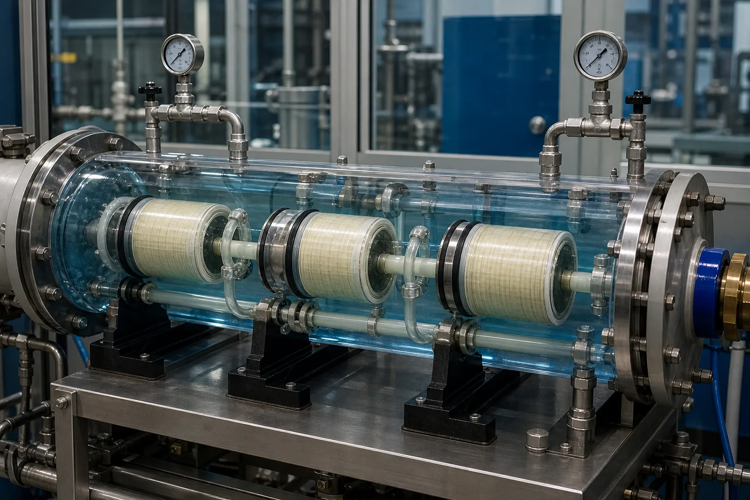 11Shell-side feed/concentrate path22Spiral element and brine seal33Permeate center tube/interconnector44End pressure, sample and piping points
What to identify
- 1Shell-side feed/concentrate path
- 2Spiral element and brine seal
- 3Permeate center tube/interconnector
- 4End pressure, sample and piping points
What this proves
Feed does not enter the center tube. That tube collects water that already crossed the membrane; concentrate advances through the feed spacer. This distinction separates spacer fouling, shell bypass and product-seal leakage.
Field check
Synchronize vessel feed/concentrate pressure and flow with permeate flow and conductivity. Use per-vessel samples or probing when needed; compare pressure drop and salt passage rather than relying only on plant-total product.
Wrapper damage, element movement and worn end seals leave different evidence
A damaged or telescoped element, fouled vessel bore and worn adapters/seals show where hydraulic shock, bypass or incorrect assembly acted.
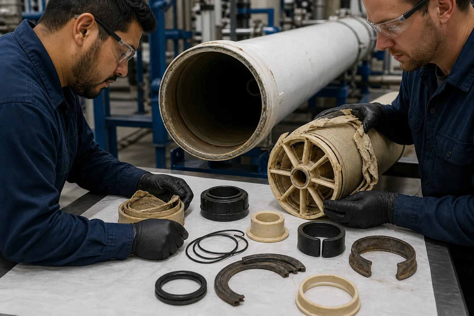 11Torn wrapper / element telescoping22Vessel bore and pressure shell33Worn end adapter / thrust hardware44O-rings, brine seal and retaining ring
What to identify
- 1Torn wrapper / element telescoping
- 2Vessel bore and pressure shell
- 3Worn end adapter / thrust hardware
- 4O-rings, brine seal and retaining ring
What this proves
Gradually rising vessel pressure drop usually points to spacer fouling or scaling. A sudden conductivity rise with stable drop suggests an interconnector, O-ring, adapter or element breach. Telescoping and end wear after starts directs attention to thrust hardware, shimming, pressure reversal and water hammer.
Field check
Preserve the element map and damage direction. Inspect the bore, grooves and every seal surface; correlate startup logs, normalized pressure drop, per-vessel conductivity and integrity results before selecting corrective work.
Three paths must close inside one vessel
The hydraulic, permeate and mechanical load paths produce different evidence when interrupted.
1 Pressurized feed
Feed port → first feed spacer
Deliver controlled pressure and flow outside the center tube.
2 Axial shell flow
Element 1 → element 2 → … → last
Carry one serial concentrate stream as salinity and risk change downstream.
3 Selective permeation
Feed spacer → membrane → permeate carrier
Pass water preferentially while retaining salts on the feed side.
4 Product collection
Carrier → center tube → connectors → outlet
Keep low-salinity permeate continuously isolated by O-rings.
5 Concentrate exit
Last element → concentrate port
Discharge retained water and control element recovery and pressure drop.
6 Axial load closure
Element train → thrust device → vessel
Transfer hydraulic thrust to the specified structure instead of misloading the head.
Inspect four functional chains separately
Pressure containment, separation, permeate sealing and axial restraint have different parts and evidence.
Shell and closures
- Normal role
- Contain pressure, close ends and connect piping
- Failure
- Shell/groove damage, head-seal leak, unseated ring, support movement
- Evidence
- Visual/dimensional inspection, full ring seating, leaks, saddle/nozzle movement, OEM record
Membrane elements
- Normal role
- Separate across feed spacer, membrane and permeate carrier
- Failure
- Fouling, scale, oxidation, wrapper rupture, telescoping or membrane damage
- Evidence
- Normalized flow/salt passage, vessel ΔP, autopsy/integrity, position and damage direction
Permeate seal train
- Normal role
- Join center tubes while excluding shell-side feed
- Failure
- Misaligned connector, cut/missing O-ring or worn end adapter
- Evidence
- Per-vessel conductivity, probing/sampling, connector/seal inspection, stable ΔP
Bypass/thrust control
- Normal role
- Brine seal stops bypass; thrust/shims limit movement
- Failure
- Wrong seal direction, play, missing thrust part, reversal/water hammer
- Evidence
- Load record, play/shims, end wear, telescoping and transient pressure
Side-port and end-port vessels from different manufacturers use different closures, thrust devices, brine-seal orientations, connector dimensions and loading steps. Use the current manuals for the exact vessel and membrane models; a generic cutaway is not an assembly instruction.
Synchronize three evidence sets
Hydraulics and recovery
Trend vessel/stage feed, concentrate and permeate flows; feed/concentrate pressure, temperature, recovery and vessel ΔP. Normalize performance to distinguish lead-end fouling, tail-end scale and channel restriction.
Water quality and integrity
Trend feed, concentrate and permeate conductivity/salinity and key ions. Sample or probe by vessel and align abrupt changes with cleaning, starts, oxidant, pH and temperature events.
Loading and mechanics
Keep element position/serial, direction, brine seal, interconnector, O-ring, thrust ring, shim and closure inventories. Inspect leaks, saddles/nozzles and startup transients.
Diagnose from signal combinations
- Signal
- Per-vessel permeate conductivity jumps while ΔP and flow barely change
- First suspicion
- Interconnector/O-ring/end-adapter leak or a mechanical element breach
- Next action
- Localize by vessel and permeate probing/sampling; after depressurization inspect product seals and integrity instead of starting with CIP
- Signal
- Vessel ΔP rises over weeks, strongest at the lead stage, while permeate flow falls
- First suspicion
- Particulate, biological or deposit loading in feed spacers
- Next action
- Check pretreatment, SDI/turbidity and biology, normalize data, select cleaning by foulant and inspect lead elements
- Signal
- Start-stop event is followed by impact, axial play, telescoping or torn wrapper
- First suspicion
- Incorrect thrust/shims, pressure reversal, water hammer or loading direction
- Next action
- Stop and depressurize; review valve timing/check valve/backpressure, then inspect thrust end, play and every position per OEM
- Signal
- External head/port leak, abnormal retaining ring or visible shell/groove damage
- First suspicion
- Pressure-boundary or closure-seal failure with safety consequence
- Next action
- Isolate, lock out and verify zero pressure; never tighten under pressure or rework the shell without qualified OEM evaluation
Four common mistakes
The vessel performs separation
The vessel contains pressure and positions parts; selective separation occurs in the membrane leaves.
Feed enters through the center tube
The center tube collects permeate; feed moves axially through the feed spacer.
The head carries all element thrust
Specified thrust hardware closes axial load; shims control play and are not arbitrary clamps.
A membrane change is just pushing in new elements
Position, direction, brine seals, connectors/O-rings, thrust parts and clearance must all be controlled.