Illustrated guide · Equipment cutaway
How does a metering pump dose chemicals precisely?
Follow the eccentric drive, stroke control, diaphragm, check valves, calibration column, backpressure valve and pulsation dampener from repeatable displacement to verified mass dose.
Direct answer
Direct answer
A diaphragm metering pump is a reciprocating positive-displacement pump. A motor, reduction gear and eccentric/crank convert rotation into repeatable diaphragm travel. On the suction stroke the diaphragm retracts, chamber volume rises, suction pressure falls, the inlet check opens and the discharge check closes. On the discharge stroke the diaphragm advances, the inlet check seats and the outlet check opens, pushing approximately one displaced volume toward the injection point. Theoretical flow is stroke volume × stroke frequency: stroke length changes volume per stroke, while speed or solenoid frequency changes strokes per minute. Actual flow also includes volumetric efficiency, which varies with pressure, valves, gas and fluid properties. Therefore a 50% setting is not automatically 50% of nameplate and is not the final dose in water. Accuracy requires a liquid-filled head, stable suction without gas pockets, fast-seating checks, stable adequate backpressure to prevent siphoning, controlled pulsation and a relief path. Calibrate with the real chemical, piping and operating backpressure over enough strokes. Then calculate mass dose from measured chemical strength × measured pump flow ÷ measured process-water flow, and verify the process response. A positive-displacement pump can rapidly overpressure a closed discharge; provide correctly routed relief and chemical-specific containment, flushing and PPE.
Four conditions make precision possible
Mechanical repeatability is only the foundation; hydraulics, calibration and the mass-dose loop must also hold.
Repeatable effective travel
Eccentric/crank, rod, stroke control and diaphragm must be free of slip, play or excessive elastic loss. Hydraulic diaphragm drives also need correct venting, oil replenishment and relief.
A liquid-filled head with fast-seating checks
Compressible gas absorbs displacement. Crystals, solids or viscous deposits prevent balls from seating. Long/high suction, viscosity and off-gassing reduce filling.
Stable differential pressure without siphon or overpressure
Low discharge backpressure can overfeed by gravity/suction; variable pressure changes delivery. Relief, damping and injection checks must be correctly selected and set.
Calibration and mass verification at real conditions
Measure calibration-column volume versus time/strokes at real fluid, temperature, suction and injection pressure; combine with active concentration and water flow for mg/L or kg/h.
A complete dosing station links storage, metering, calibration, pressure control and injection
Two mechanical diaphragm pumps draw from a bunded chemical tank; clear columns provide a volume standard, pressure accessories protect discharge, and chemical enters the process pipe at the injection point.
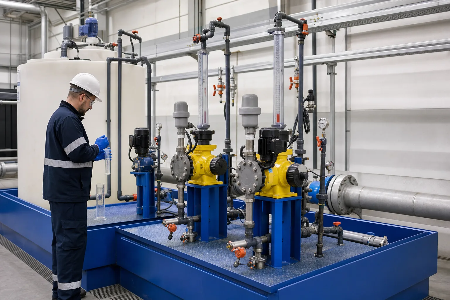 11Chemical tank, suction and bund22Diaphragm metering pump/drive33Calibration column and isolation44Damping/backpressure/relief and injection
What to identify
- 1Chemical tank, suction and bund
- 2Diaphragm metering pump/drive
- 3Calibration column and isolation
- 4Damping/backpressure/relief and injection
What this proves
The pump is one link. Suction air leaks, wrong calibration-valve positions, low backpressure, relief recirculation or a crystallized injection check can leave the drive running without delivering the commanded dose.
Field check
Verify chemical/strength/material compatibility, containment and low level; inspect foot/strainer, calibration piping, backpressure/relief return, dampener precharge and injection check; perform an actual volumetric calibration.
The cutaway converts eccentric rotation into diaphragm displacement while two checks enforce direction
Motor and gearing drive an eccentric and rod; stroke adjustment changes effective travel. The diaphragm isolates the power end, with discharge and suction ball checks above and below.
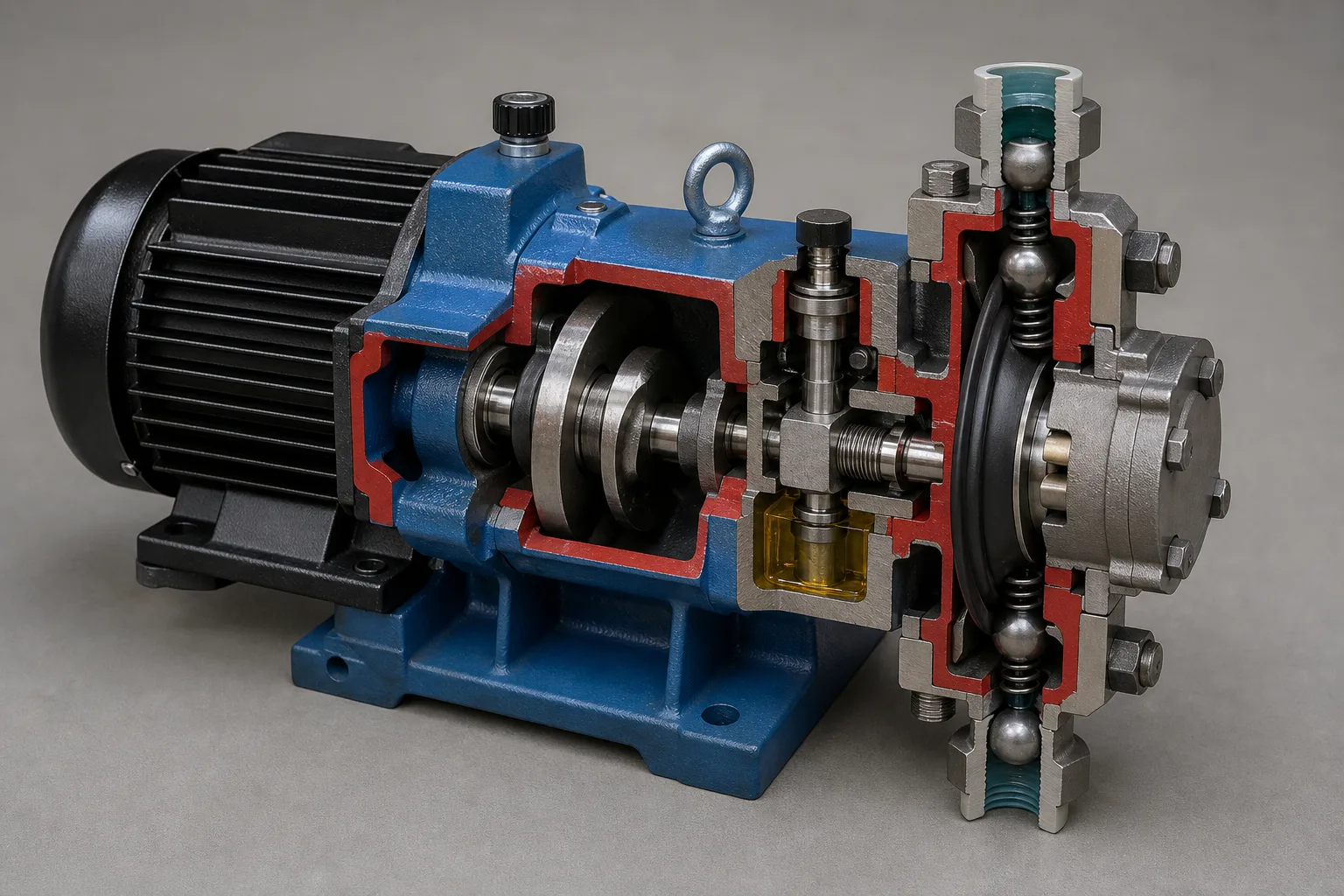 11Motor, reduction and eccentric22Stroke control, rod and return33Diaphragm and displaced chamber44Discharge/suction ball checks
What to identify
- 1Motor, reduction and eccentric
- 2Stroke control, rod and return
- 3Diaphragm and displaced chamber
- 4Discharge/suction ball checks
What this proves
Accuracy is repeatable volume, not steady instantaneous flow. Each cycle pulses. If a ball does not seat, travel is lost to backflow while the displayed stroke remains unchanged.
Field check
Use the OEM curve for stroke, frequency and backpressure. Trend valve noise, pressure pulsation and motor load; at service record linkage play, diaphragm condition, ball/seat orientation and spring specification.
A transparent pair freezes the suction and discharge strokes
One diaphragm retracts as the bottom check opens and top check seats; the other advances as the inlet seats and outlet opens. Clear tubing shows bubbles and column response.
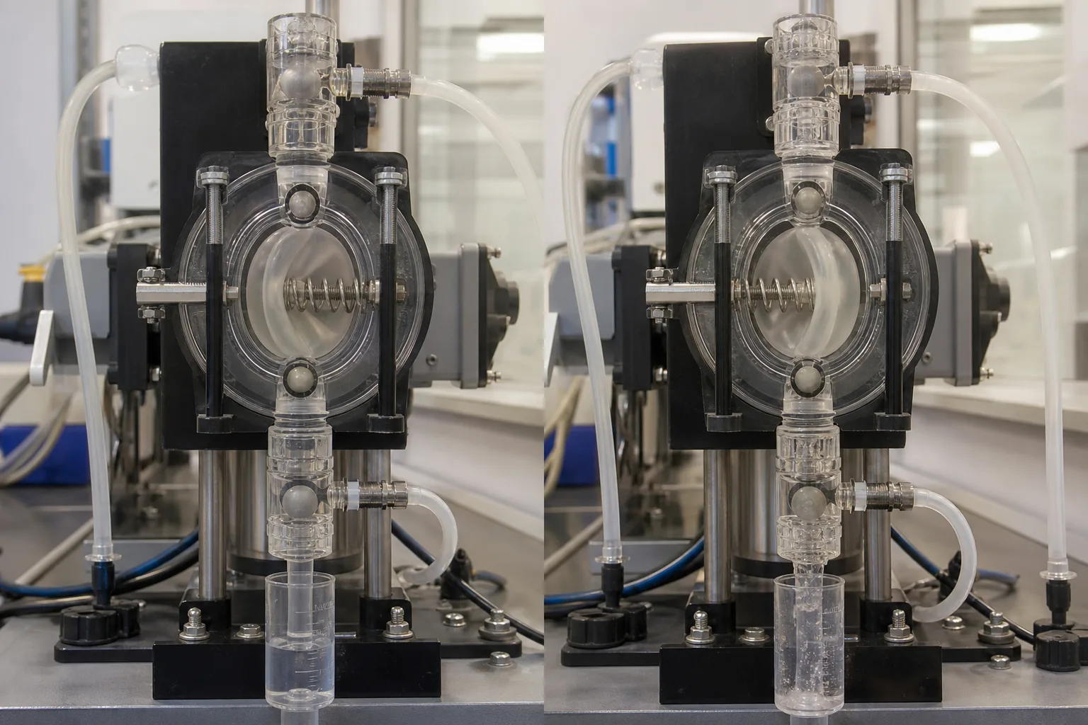 11Suction stroke: diaphragm retracts22Bottom inlet check opens/seats33Discharge stroke: diaphragm advances44Top outlet check seats/opens
What to identify
- 1Suction stroke: diaphragm retracts
- 2Bottom inlet check opens/seats
- 3Discharge stroke: diaphragm advances
- 4Top outlet check seats/opens
What this proves
Checks switch on differential pressure. A small gas pocket behaves like a spring, repeatedly compressing and expanding, so diaphragm motion may not generate enough valve differential: gas lock or intermittent output follows.
Field check
Prime/vent only by the allowed procedure. Confirm arrows and ball/spring orientation and route suction without gas traps. Use an OEM degassing head or slow-suction mode for off-gassing fluids.
Calibration comparison shows how prime, gas, valves and backpressure change flow at the same setting
Four pumps discharge to graduated cylinders: a repeatable liquid column, intermittent bubbly flow, low/no delivery and abnormal overfeed/siphon produce visibly different measured volumes.
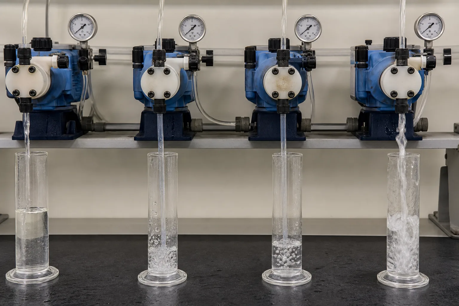 11Fully primed repeatable delivery22Gas/off-gassing intermittent flow33Lost prime or check leakage44Low backpressure / siphon overfeed
What to identify
- 1Fully primed repeatable delivery
- 2Gas/off-gassing intermittent flow
- 3Lost prime or check leakage
- 4Low backpressure / siphon overfeed
What this proves
The column reading is the actual flow for that condition. Accumulate enough strokes and repeat at stable backpressure; short tests magnify pulse and scale error. Recalibrate after fluid, pressure, suction, stroke range or wet-end work changes.
Field check
Start at a known column level, isolate tank suction while keeping the real discharge connected, and measure volume difference over time/strokes without emptying the column. Restore valves and log temperature, pressure, settings and repeats.
A cracked diaphragm, dirty checks and aged seals turn repeated strokes into leaks or backflow
The technician exposes a cracked/contaminated diaphragm; balls, seats, springs, rod and O-rings lie in the tray while leak ports or rupture detection provide warning.
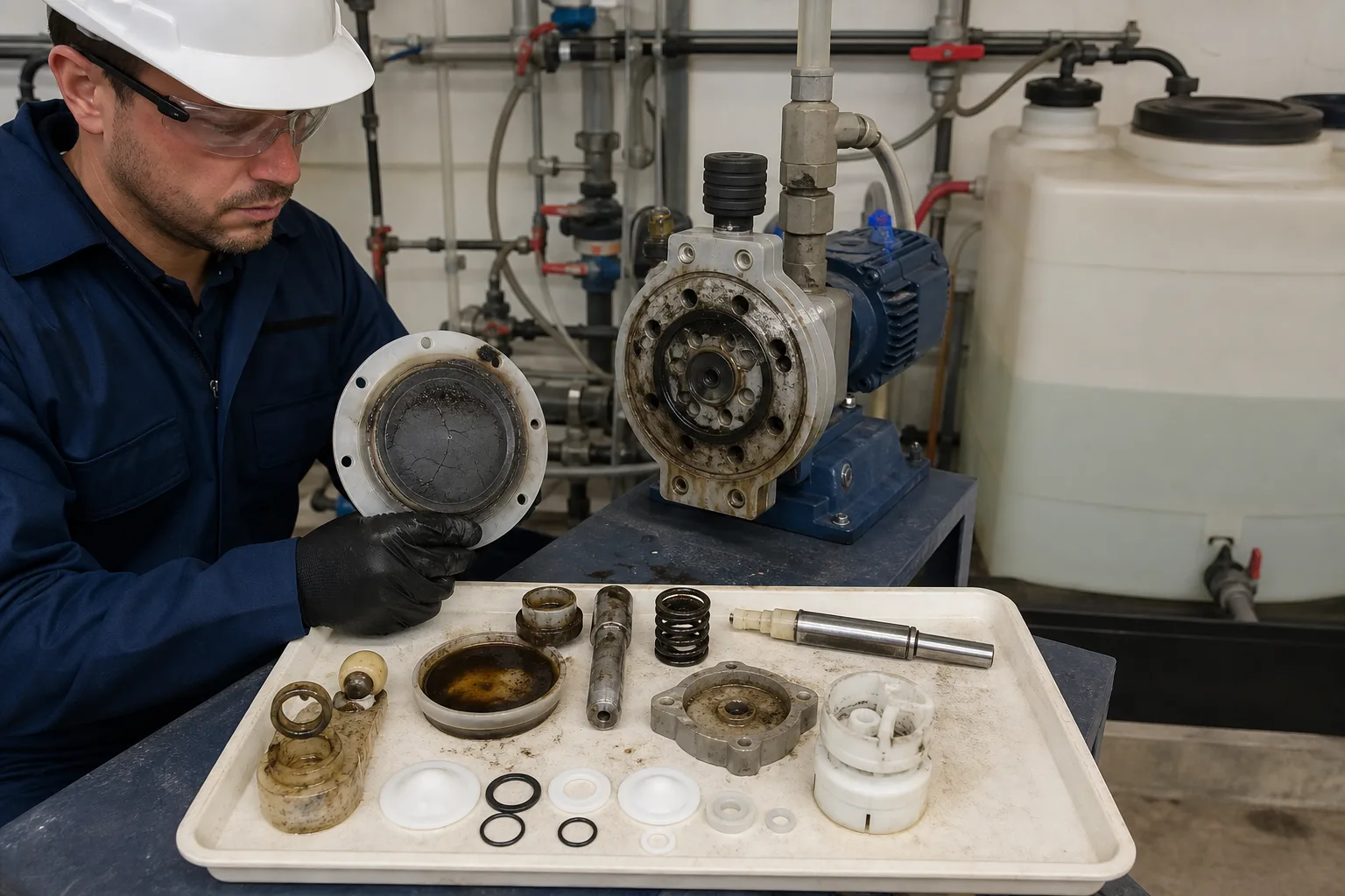 11Cracked/permeated diaphragm22Check balls, seats and springs33Rod/hydraulic compensation and return44O-rings, gaskets and leak detection
What to identify
- 1Cracked/permeated diaphragm
- 2Check balls, seats and springs
- 3Rod/hydraulic compensation and return
- 4O-rings, gaskets and leak detection
What this proves
Diaphragm failure can underdose, release hazardous chemical into the drive, or contaminate process with hydraulic oil. A small crystal on a seat causes material backflow. Never compensate for a rupture alarm by increasing stroke.
Field check
Stop, de-energize, close suction/discharge, relieve line pressure, and flush/neutralize per SDS. Replace compatible wet-end sets at correct torque; test containment/rupture detection and recalibrate after repair.
Six steps from one stroke to an auditable dose
Mechanical displacement, actual liquid volume and process mass concentration are different measurement layers.
1 Command
Manual/pulse/4–20 mA/ratio → length and frequency
Convert process demand into motion with limits and fault state.
2 Fill
Tank → foot/strainer → inlet check → chamber
Fill the next stroke with a low-loss, gas-free liquid column.
3 Displace
Drive → diaphragm → smaller chamber
Create differential pressure to open the outlet against injection pressure.
4 Condition/inject
Outlet → dampener/backpressure/relief → injection check
Manage pulses, siphon and overpressure at the correct mixing point.
5 Calibrate
Volume change ÷ time or strokes
Measure current L/h and delivered volume per stroke.
6 Close mass loop
Strength × measured flow ÷ water flow → response
Calculate dose and verify residual, pH, ORP or target quality.
Verify four functional chains separately
Drive repetition, wet-end displacement, piping hydraulics and mass calculation fail differently.
Drive/stroke
- Normal role
- Repeat motion and modulate length/frequency
- Failure
- Eccentric/gear/rod wear, slipping adjuster, motor/solenoid heat, hydraulic refill fault
- Evidence
- Stroke/position, speed/current, scale, play, oil/temperature and alarms
Diaphragm/checks
- Normal role
- Define chamber displacement and one-way flow
- Failure
- Fatigue/rupture, stuck/worn ball, crystallized seat, wrong direction
- Evidence
- Calibrated stroke volume, valve sound/backflow, leak/rupture alarm and teardown
Suction/discharge
- Normal role
- Maintain filling and differential, control pulse/siphon/overpressure and inject
- Failure
- Air/restriction, low/variable backpressure, lost dampener charge, failed relief/check
- Evidence
- Pressure waveform, bubbles, calibrated flow, relief return, precharge and injection point
Dose/process
- Normal role
- Turn measured flow, active strength and water flow into mass dose/feedback
- Failure
- Degraded/diluted chemical, bad main-flow signal, ratio/unit error, poor mixing/demand shift
- Evidence
- Batch strength, L/h, water m³/h, kg/h or mg/L, residual/pH/ORP and quality
Accuracy, turndown and minimum recommended stroke apply only inside model-specific pressure, stroke, fluid and installation limits. Do not generalize one pump's ±1% claim or low-stroke behavior; use its performance curve and verify repeatability/linearity in the field.
Synchronize three evidence sets
Command and motion
Log run/stop, length, frequency/strokes per minute, pulse or 4–20 mA command/feedback, current, rupture/flow monitor and interlocks.
Hydraulics and measured flow
Log tank level/temperature, suction/discharge pressure waveform, backpressure, column volume/time/strokes, venting and relief return; recalibrate after changes.
Mass dose and response
Log batch active strength, measured L/h, main-water flow and calculated kg/h or mg/L on the same timeline as residual, pH, ORP or target pollutant.
Locate faults across command, flow and process result
- Signal
- Strokes are audible but the calibration level barely or intermittently falls and discharge pressure is low
- First suspicion
- Gas lock, suction air/low level, stuck inlet check or excessive suction loss
- Next action
- Prime/vent safely; inspect level, foot/strainer, airtight joints, lift/diameter, viscosity and off-gassing before increasing stroke
- Signal
- Measured flow is low and pressure-dependent with backflow noise
- First suspicion
- Dirty/worn check, diaphragm/hydraulic fault or operation beyond pressure rating
- Next action
- Compare at stable pressures; after isolation inspect check orientation/cleanliness, diaphragm and model pressure curve
- Signal
- Measured flow is high and chemical continues after the pump stops
- First suspicion
- Siphon/negative process pressure, failed backpressure or injection check, excessive tank head
- Next action
- Isolate and verify differential; repair anti-siphon/backpressure and injection check—never offset stop-flow by lowering the setpoint
- Signal
- Pump calibration is correct but residual/target response is low or variable
- First suspicion
- Active strength, main-flow signal/ratio/units, mixing or process demand
- Next action
- Retest strength and main flow, recalculate mass dose, close a short material balance and inspect injection/mixing and analyzers
Four common mistakes
50% setting means 50% nameplate flow
Actual flow depends on length/frequency, pressure, filling and valve efficiency; calibrate it.
Motion guarantees chemical flow
Gas lock, suction air or stuck checks allow diaphragm motion with near-zero net delivery.
Zero backpressure is most accurate
Too little can siphon and overfeed; stable OEM-range differential supports check operation.
Correct L/h means correct dose
Mass dose also depends on active strength, water flow, mixing and reaction demand.