Illustrated guides · Equipment cutaways
How does a multistage centrifugal pump build pressure stage by stage?
One stream passes through successive impeller-diffuser stages: impellers add shaft energy, stationary passages recover velocity and feed the next eye, and stage heads add in series.
Direct answer
Direct answer
A multistage centrifugal pump behaves like several single-stage pumps in series on one shaft. Water enters the first impeller eye axially. The rotating impeller transfers shaft work, raising angular momentum, velocity, and total head. Stationary diffuser and return passages then decelerate and redirect the flow, converting part of velocity head to static pressure and delivering the right inlet direction to the next impeller. The same flow passes through every stage, so stage heads—not flow rates—add. With similar stages, ideal total head is roughly stage count times single-stage head, minus disk-friction, leakage, diffusion, and return losses. Head is energy per unit liquid weight; for a given geometry, speed, and flow it is nearly density-independent, while pressure rise follows Δp≈ρgH and power rises with density. The actual duty point is not forced by nameplate pressure: it is the intersection of the pump H–Q curve and the system curve. Under similarity conditions, speed changes approximately follow Q∝n, H∝n², and P∝n³. More stages increase head capability but also axial thrust, leakage surfaces, rotor length, tolerance stack, and seal/bearing duty. Suction NPSH remains critical at the first stage; cavitation commonly begins there and causes noise, vibration, head loss, and pitting.
Four conditions make stage-by-stage pressure rise work
More impellers do not automatically mean efficient high pressure; suction, interstage conversion, duty point, and mechanics must all work.
Give the first stage adequate, even suction energy
NPSHA needs suitable margin above manufacturer NPSHR/NPSH3. Blockage, low level, heat, air ingress, or a close elbow can damage the first stage.
Match impellers and diffusers with low leakage
The impeller adds energy; the diffuser recovers velocity and redirects. Wear-ring, interstage-seal, and assembly errors recirculate that energy.
Intersect the system curve in a sound operating region
Near BEP and within the preferred/allowable region, incidence, hydraulic loads, recirculation, vibration, and energy are normally better controlled.
Carry cumulative thrust and driver load
Stage pressure creates axial thrust and raises demands on shaft, balancing device, bearings, seals, coupling, and motor power.
A full multistage pump train combines suction header, pump, motor, VFD, and discharge control
A large stainless header feeds several horizontal barrel pumps; stages sit in the long casing, blue motors and rear VFDs drive them, and actuators/instruments control discharge.
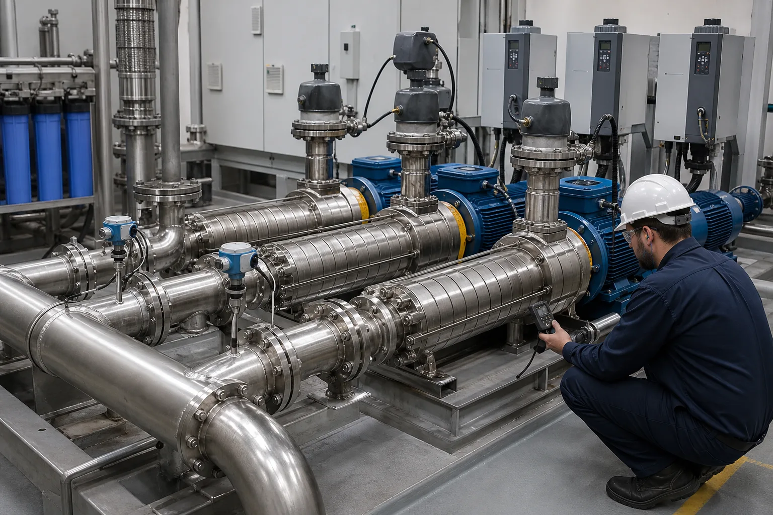 11Low-loss suction header/instrumentation22Horizontal multistage barrel/casing33Motor, coupling, and VFD44Discharge check/isolation and pressure control
What to identify
- 1Low-loss suction header/instrumentation
- 2Horizontal multistage barrel/casing
- 3Motor, coupling, and VFD
- 4Discharge check/isolation and pressure control
Figure takeaway
Pressure is generated inside the pump, but the system sets the duty point. Parallel pumps mainly extend flow capacity; stages inside each pump mainly extend head capacity.
How to verify it in the field
Time-align suction/discharge absolute pressure, flow, speed, power, valve position, and pumps online. Calculate head/efficiency and check suction-filter loss, air ingress, check valves, and VFD limits.
The cutaway pairs each rotating impeller with a stationary diffuser/return passage
The left inlet feeds the first eye; several impellers share a shaft, fixed passages surround them, and the upper-right collector receives final high-pressure water.
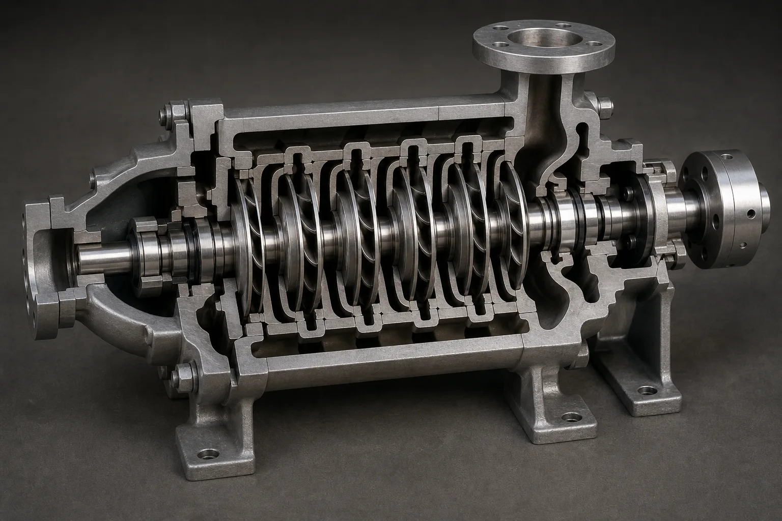 11Axial suction and first-stage eye22Common-shaft impeller train33Stationary diffuser and return passages44Final collector and high-pressure discharge
What to identify
- 1Axial suction and first-stage eye
- 2Common-shaft impeller train
- 3Stationary diffuser and return passages
- 4Final collector and high-pressure discharge
Figure takeaway
An impeller does not simply squeeze water. It raises total energy and velocity; stationary passages diffuse, recover pressure, and condition the next-stage inlet. The cycle repeats.
How to verify it in the field
Confirm flow direction, rotation, stage count, and return-piece orientation from the OEM section. Record diameters, wear-ring clearances, interstage seals, fits, and assembly direction.
The teardown shows why high head depends on alignment, interstage clearances, thrust, and seals
The shaft carries staged rotating parts; segmented casings/return pieces, wear rings, bearings, sleeves, and seals are arranged below, with pressure casings at both ends.
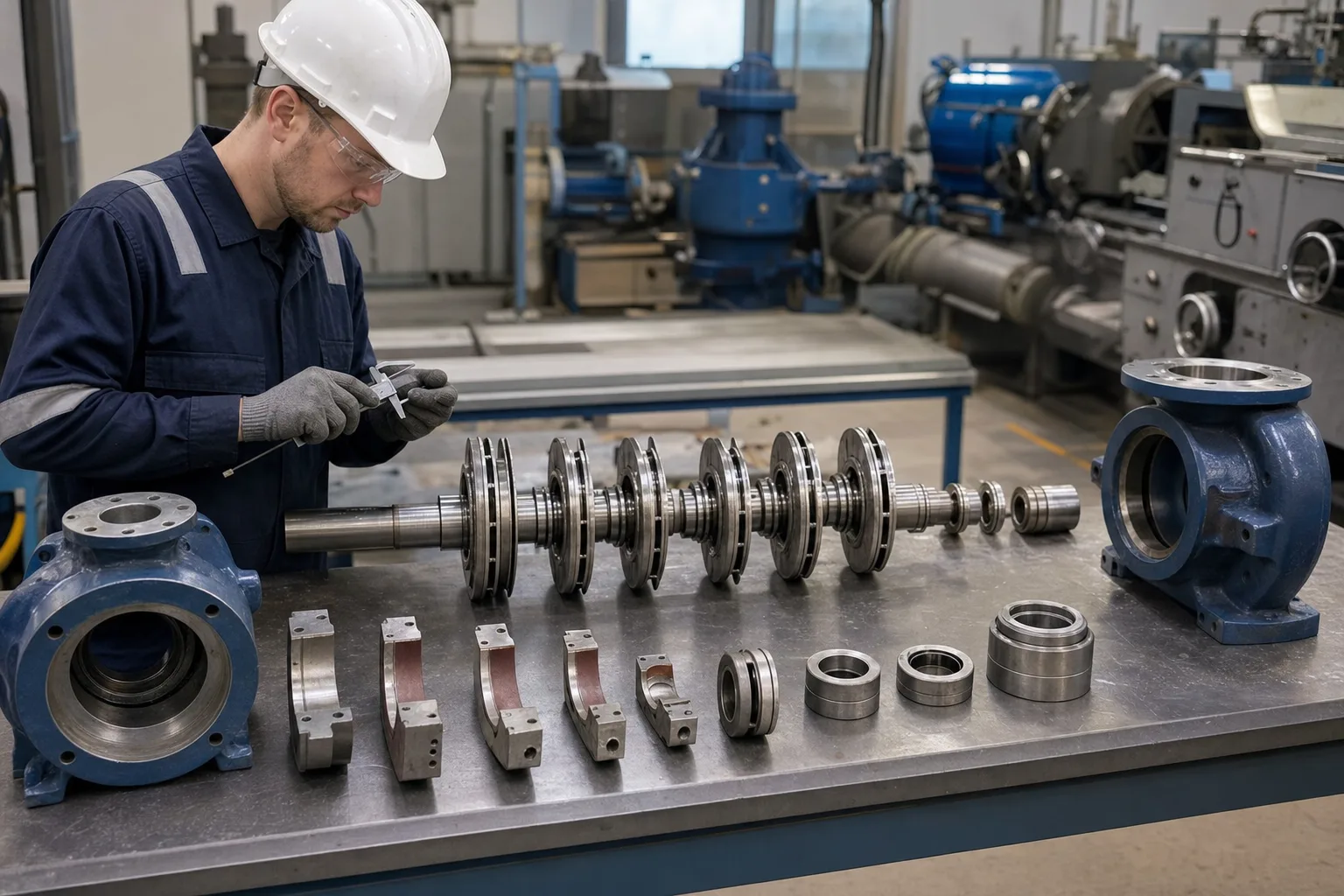 11Shaft and stacked impeller rotor22Segmental casing/diffuser-return pieces33Wear rings, sleeves, seals, bearings44Suction- and discharge-end pressure casings
What to identify
- 1Shaft and stacked impeller rotor
- 2Segmental casing/diffuser-return pieces
- 3Wear rings, sleeves, seals, bearings
- 4Suction- and discharge-end pressure casings
Figure takeaway
More stages make tolerance stack, deflection, leakage, and axial position more sensitive. A reversed return piece or enlarged wear ring can leave the pump turning but short of head.
How to verify it in the field
Measure shaft straightness, impeller positions, ring/sleeve clearances, bearing play, seal faces, and balance-device clearance. Preserve stage order/orientation; hand-turn, align, and pressure/leak test.
A transparent test pump shows total head rising across successive stage taps
A reservoir and clear suction elbow feed visible stages; pressure taps and gauges follow the train, while a discharge flow column, coupling, and motor close the test loop.
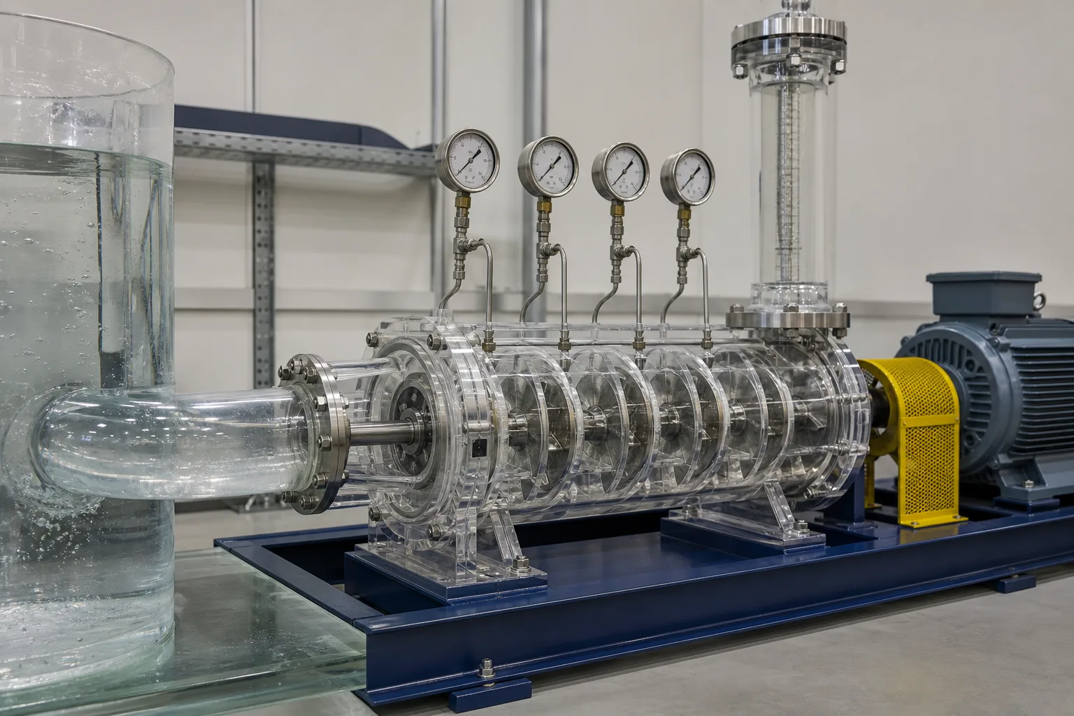 11Reservoir, suction bend, first-stage inlet22Transparent impeller-diffuser stages33Interstage pressure taps and gauges44Discharge flowmeter, coupling, motor
What to identify
- 1Reservoir, suction bend, first-stage inlet
- 2Transparent impeller-diffuser stages
- 3Interstage pressure taps and gauges
- 4Discharge flowmeter, coupling, motor
Figure takeaway
Pressure normally rises stage by stage, but increments vary with inlet swirl, distance from BEP, clearances, and passage loss. Gauge data require a common datum plus velocity/elevation correction.
How to verify it in the field
Calibrate taps and record stable flow, speed, temperature/density, pipe size, and elevation. Calculate stage/total head and map H–Q, efficiency, power, and suction behavior—not just shutoff pressure.
Cavitation pitting, wear-ring leakage, and bearing/seal faults waste energy differently
Technicians compare a pitted/deposited impeller, worn rings, sleeves, bearings, and seals while dimensional and vibration tools connect appearance to operating evidence.
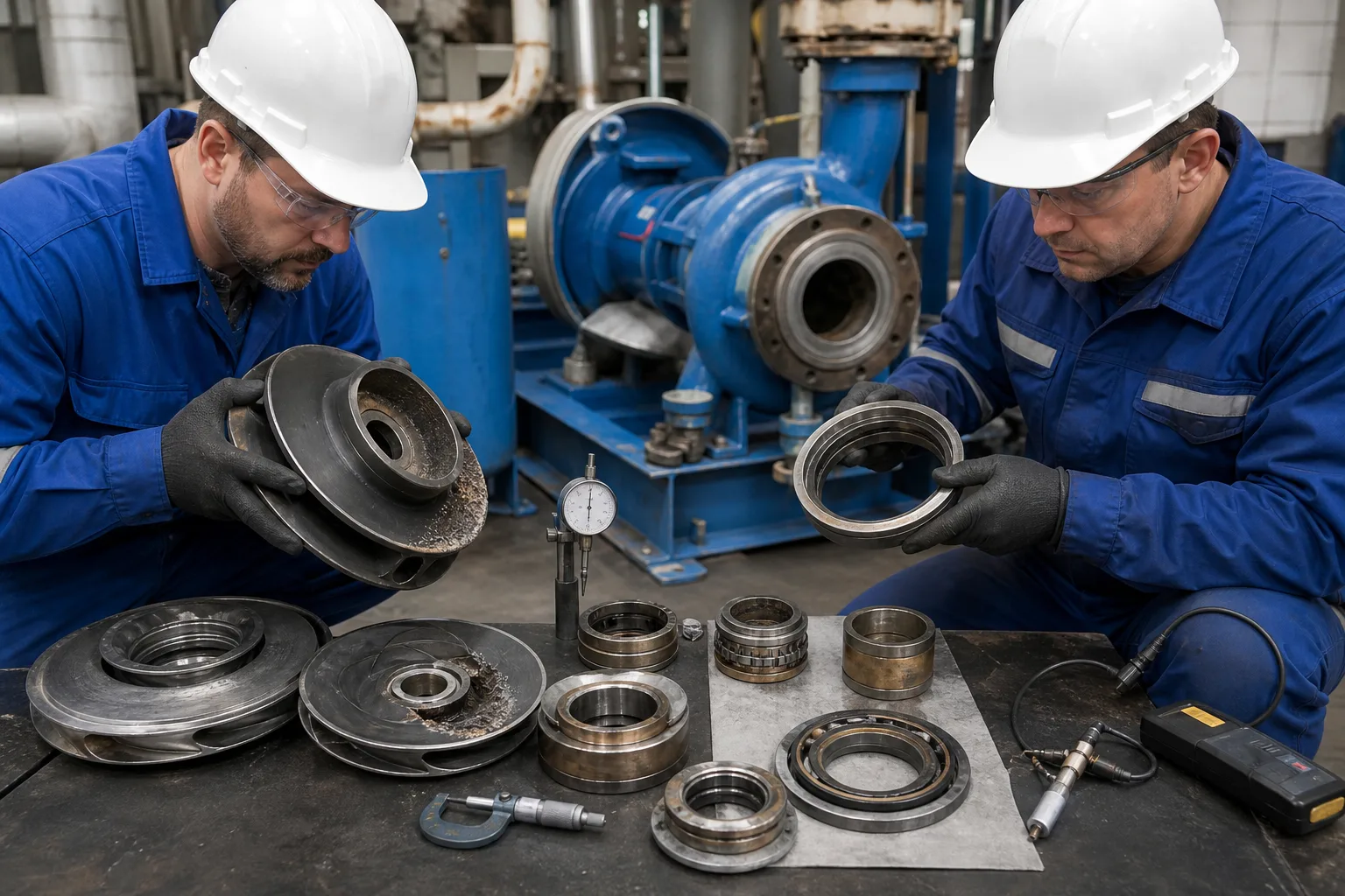 11First-stage impeller cavitation/deposit22Worn ring and internal-leakage clearance33Sleeves, bearings, and mechanical seal44Dimensional, runout, and vibration evidence
What to identify
- 1First-stage impeller cavitation/deposit
- 2Worn ring and internal-leakage clearance
- 3Sleeves, bearings, and mechanical seal
- 4Dimensional, runout, and vibration evidence
Figure takeaway
Falling head does not mean add stages. First-stage cavitation attacks the inlet; wear clearances recirculate head internally; bearing/alignment faults add friction and vibration. Each needs a different response.
How to verify it in the field
Lock out, depressurize, and drain. Compare normalized flow/head/power, NPSH margin, and vibration spectrum, then measure pitting, clearances, runout, bearing play, seal leakage, and alignment.
Six energy steps through one stage
Each stage repeats the conversion; the next stage receives higher total head, not more flow.
1 Enter eye
Suction header → first impeller eye
Provide even flow with adequate NPSH.
2 Add shaft work
Motor → shaft → rotating impeller → liquid
Raise momentum, velocity, and total head.
3 Diffuse
High-speed water → stationary diffuser
Convert some velocity head to static pressure.
4 Return/condition
Return passage → next impeller eye
Reduce swirl and match inlet angle.
5 Add stages
Htotal≈ΣHstage−losses
Raise head at the same series flow.
6 Meet system
Final collector → system-curve intersection
Overcome static and friction head at actual flow.
Four functional parts of a multistage pump
Suction, hydraulic stages, rotor support, and system control need separate evidence.
Suction/first stage
- Role
- Provide even, gas-free flow and NPSHA
- Typical failure
- Low level, blockage, air, heat, preswirl, cavitation
- Evidence
- Absolute suction pressure, temperature, level/loss, margin, noise/vibration, first-stage pitting
Impeller-diffuser stages
- Role
- Add work, diffuse, redirect, and sum head
- Typical failure
- Damage, internal leakage, reversed/blocked stage
- Evidence
- Stage pressure, H–Q/efficiency, clearances, passages, restored test
Shaft/thrust/seals
- Role
- Keep alignment, carry radial/axial loads, contain pressure
- Typical failure
- Misalignment, bearing/balance wear, deflection, seal leak
- Evidence
- Vibration/temp/axial position, runout/alignment, oil, leakage
Driver/system control
- Role
- Provide speed/power within system and operating region
- Typical failure
- Chronic throttle, wrong speed/valves, overload, low-flow recirculation
- Evidence
- Flow/head/speed/power/valves, BEP offset, minimum flow, parallel curves
Use manufacturer curves and applicable standards for NPSH margin, POR/AOR, minimum continuous stable flow, axial-thrust limits, maximum stages/speed, and seal pressure. NPSHR/NPSH3 is a specified performance-drop criterion, not zero cavitation.
Align three datasets at one duty point
Hydraulics/duty
Suction/discharge absolute pressure, flow, temperature/density, speed, valves, static head, and pipe losses; calculate head and overlay pump/system curves.
Energy/driver
Voltage, current, power factor, input/shaft power, VFD frequency, pump efficiency, specific energy, and location relative to BEP/AOR.
Reliability/inspection
Vibration spectrum, bearing/seal temperature, leakage, noise, axial position, oil, first-stage pitting, ring clearance, alignment, and hours.
Layer the diagnosis when pressure or flow is low
- Combined signal
- Suction pressure falls, gravel-like noise and vibration rise, first/total head fluctuates
- Likely cause
- Low NPSH, air ingress, or suction blockage causing first-stage cavitation
- Next step
- Reduce load; check level, temperature, filter loss, valves, leaks, and NPSHA margin—do not add speed
- Combined signal
- Same flow but head declines over months, power may not follow, stage distribution changes
- Likely cause
- Wear-ring/interstage leakage or damaged/blocked impeller/diffuser
- Next step
- Normalize trends, run stage/performance tests, then inspect clearances and passages
- Combined signal
- Head is near normal but power, bearing heat, and characteristic vibration rise
- Likely cause
- Alignment, bearing, thrust-balance, or rotor rub
- Next step
- Check alignment, soft foot, lubrication, axial position/balance device, and rubs
- Combined signal
- Pump curve can meet duty but field runs low-flow/high-head with chronic throttle/bypass
- Likely cause
- Pump-system mismatch or poor control
- Next step
- Rebuild system curve and assess speed, impeller/stage selection, or train configuration
Four common misconceptions
Every added stage also adds flow
Stages carry the same series flow and add head; parallel pumps mainly add flow capability.
The impeller converts all velocity directly to pressure
The impeller transfers shaft work; stationary diffusers recover velocity and redirect flow.
The same head means the same pressure and power for any liquid
Pressure rise scales with density and viscosity alters losses/curves; verify the driver.
Meeting NPSHR means no cavitation
NPSH3 is defined at a 3% first-stage head drop; reliable service normally requires specified margin.