Illustrated guides · Physicochemical treatment
How does dissolved-air flotation use microbubbles to remove contaminants?
DAF does not simply sparge ordinary large bubbles. It dissolves air into pressurized recycle, releases microbubbles at atmospheric pressure, attaches them to conditioned solids, then skims the floating layer.
Direct answer
Direct answer
Dissolved-air flotation usually withdraws a clarified recycle stream, pressurizes it and contacts it with air in a saturation vessel so air dissolves at elevated pressure. When that stream passes through a release device into the atmospheric flotation tank, dissolved air nucleates as a dense cloud of microbubbles or whitewater. The bubbles collide with and attach to coagulated floc, oil droplets or algae, and may also become trapped inside floc. Their buoyancy lowers the aggregate's apparent density, so bubble–floc complexes rise into a surface float layer that a skimmer removes while clarified water leaves below. Performance depends on feed solids/oil, coagulation and flocculation, saturation efficiency, pressure, recycle ratio, air-to-solids ratio, release condition, total hydraulic and solids loading, basin flow pattern, skimming and float depth. Higher pressure, more air and more recycle are not unlimited improvements.
Four linked conditions make microbubble separation work
A white or bubbling surface does not prove that bubble size, attachment and float removal are correct.
Air first dissolves into recycle
The saturator needs suitable pressure, contact, residence and level. Pump air ingestion, excess gas pockets or pressure cycling can reduce dissolved air despite high indicated supply.
Release creates a uniform microbubble cloud
Wear, plugging, insufficient pressure drop or poor distribution produces large bubbles, dead zones or jets and reduces collision/attachment.
Floc accepts bubbles and survives release shear
Unstable fines do not form robust complexes, while oversized loose floc can break in the release zone. Chemistry and shear must be optimized for flotation, not copied from settling.
Float is removed before it returns
A thin layer can be watery and over-skimmed; an excessive layer can compress, sink, turn septic or recirculate. Skimmer speed, trough elevation, level and effluent withdrawal interact.
Full-scale DAF closes the loop between recycle saturation, release, float and skimming
The pressure vessel and pumps treat clarified recycle, piping delivers it to release, white surface zones show bubbles and rising floc, and the end skimmer moves float to a trough.
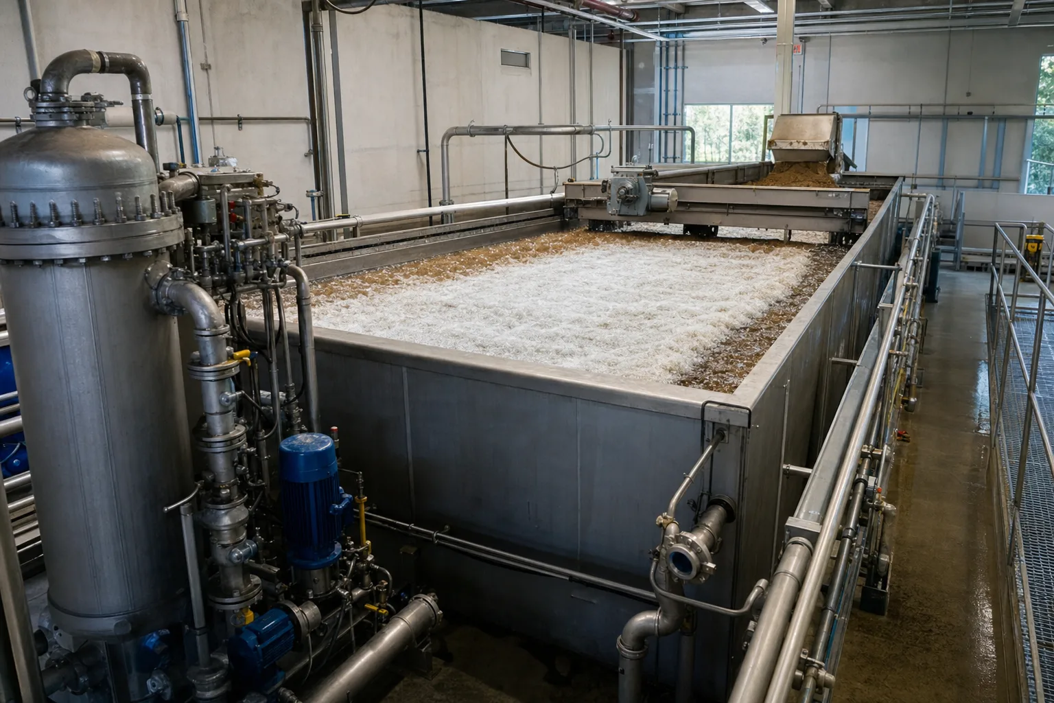 11Saturator and recycle pump22Whitewater release/contact zone33Surface float blanket44Skimmer and float trough
What to identify
- 1Saturator and recycle pump
- 2Whitewater release/contact zone
- 3Surface float blanket
- 4Skimmer and float trough
What the image proves
The tank cannot work alone. Recycle, air supply, saturation, release, contact, separation and skimming each determine bubble quantity/size, attachment opportunity or float residence.
How to verify on site
Trace recycle source, flow/pressure, saturator pressure/level/vent and release pressure drop/whitewater distribution; log float depth, skimming cycle, float discharge and clarified TSS/turbidity.
Microscopically, bubbles do not push solids; attached complexes rise together
A mechanism visualization shows bubbles attached to floc, free bubbles and several rising bubble–floc complexes. It is not a literal micrograph of one contaminant.
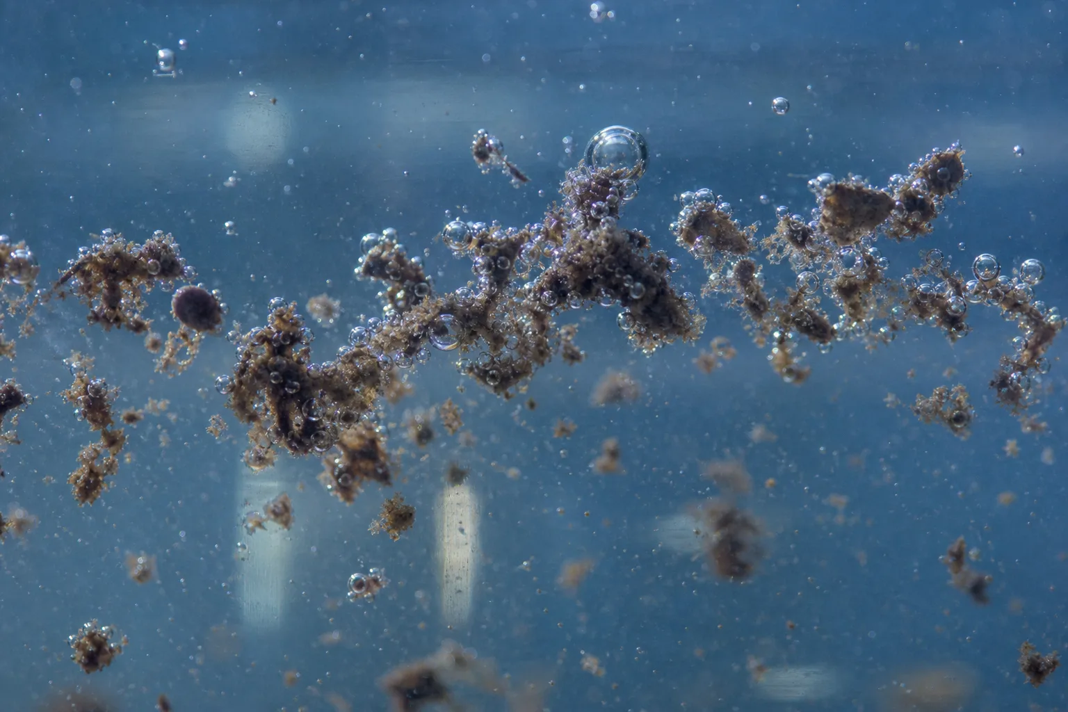 11Floc or oil-droplet core22Attached microbubbles33Free unattached bubbles44Low-density rising complex
What to identify
- 1Floc or oil-droplet core
- 2Attached microbubbles
- 3Free unattached bubbles
- 4Low-density rising complex
What the image proves
Bubbles must be small enough to provide high area and collision opportunity, yet remain attached. Large bubbles rise quickly, contact briefly and can pass through; more bubbles without better floc or attachment can still leave turbid effluent.
How to verify on site
Observe fine, even whitewater and continuous rising floc; where available compare bubble/floc imaging, then judge rise rate, supernatant particles and float solids.
A transparent pilot shows saturation, release, attachment and clarified withdrawal together
The vertical pressure vessel is the saturator, the bottom pump pressurizes recycle, the central cloud enters contact, float collects above and clearer water leaves at left.
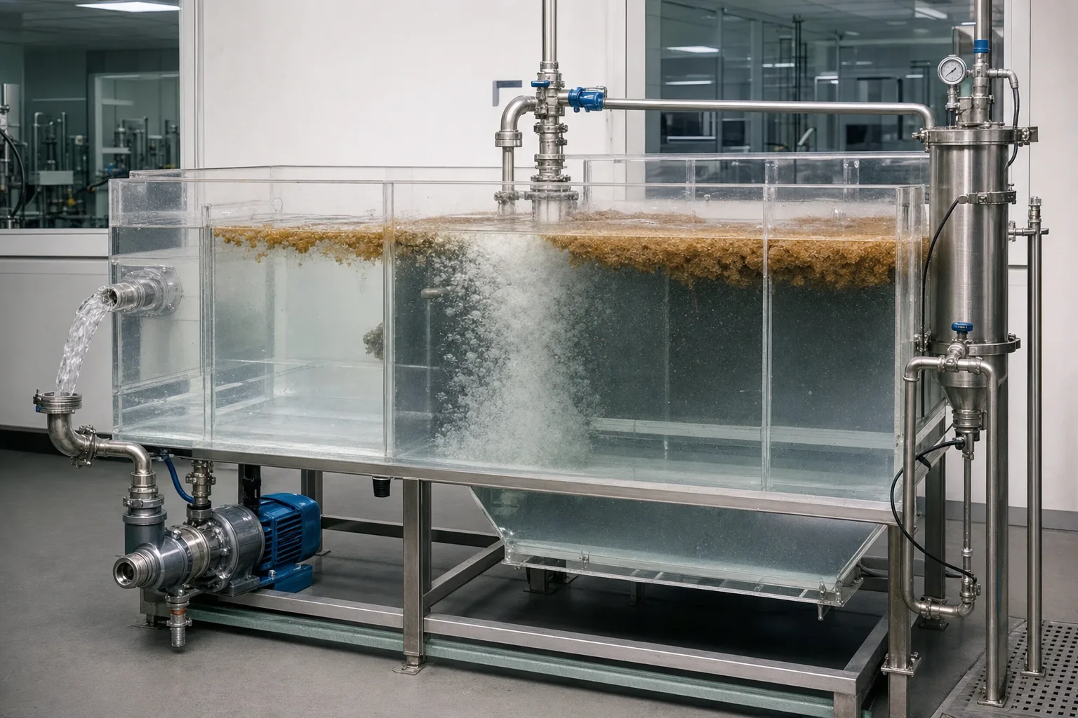 11Recycle pump/pressurized water22Pressure saturation vessel33Release device/whitewater44Float layer/clarified outlet
What to identify
- 1Recycle pump/pressurized water
- 2Pressure saturation vessel
- 3Release device/whitewater
- 4Float layer/clarified outlet
What the image proves
Recycle ratio supplies air but also adds hydraulic load. Saturation pressure matters only if the release device converts dissolved air into useful bubbles. One adjustment changes air-to-solids, hydraulics and residence at once.
How to verify on site
Calculate total hydraulic loading from influent plus measured recycle; log pressure, air, temperature and pre/post-release pressure, and sample contact, separation, float and clarified streams.
Side-by-side tests separate low air, a useful whitewater window and bubble–floc mismatch
One column rises slowly and stays turbid, the middle forms fine bubbles and stable float, and the third rolls or retains solids from overload, large bubbles or poor chemistry/shear.
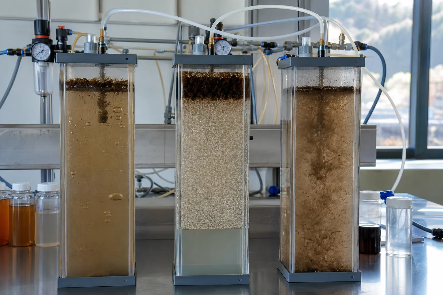 11Low air/slow flotation22Fine whitewater/stable float33Overload or bubble–floc mismatch44Three same-feed candidates
What to identify
- 1Low air/slow flotation
- 2Fine whitewater/stable float
- 3Overload or bubble–floc mismatch
- 4Three same-feed candidates
What the image proves
The whitest column is not automatically best. Low air cannot float solids; excessive air/recycle can increase turbulence and bubble carry-through; poor chemistry leaves no stable surface for attachment.
How to verify on site
At constant feed/chemistry, test pressure, recycle or air-to-solids gradients and measure flotation time, clarified turbidity/TSS/particles, float depth and solids; then cross-test chemistry and release shear.
Surface diagnosis must connect skimming, effluent samples and recycle equipment
An operator compares clarified samples beside a skimmer pushing mature float to collection; background equipment links surface appearance to pressure and recycle evidence.
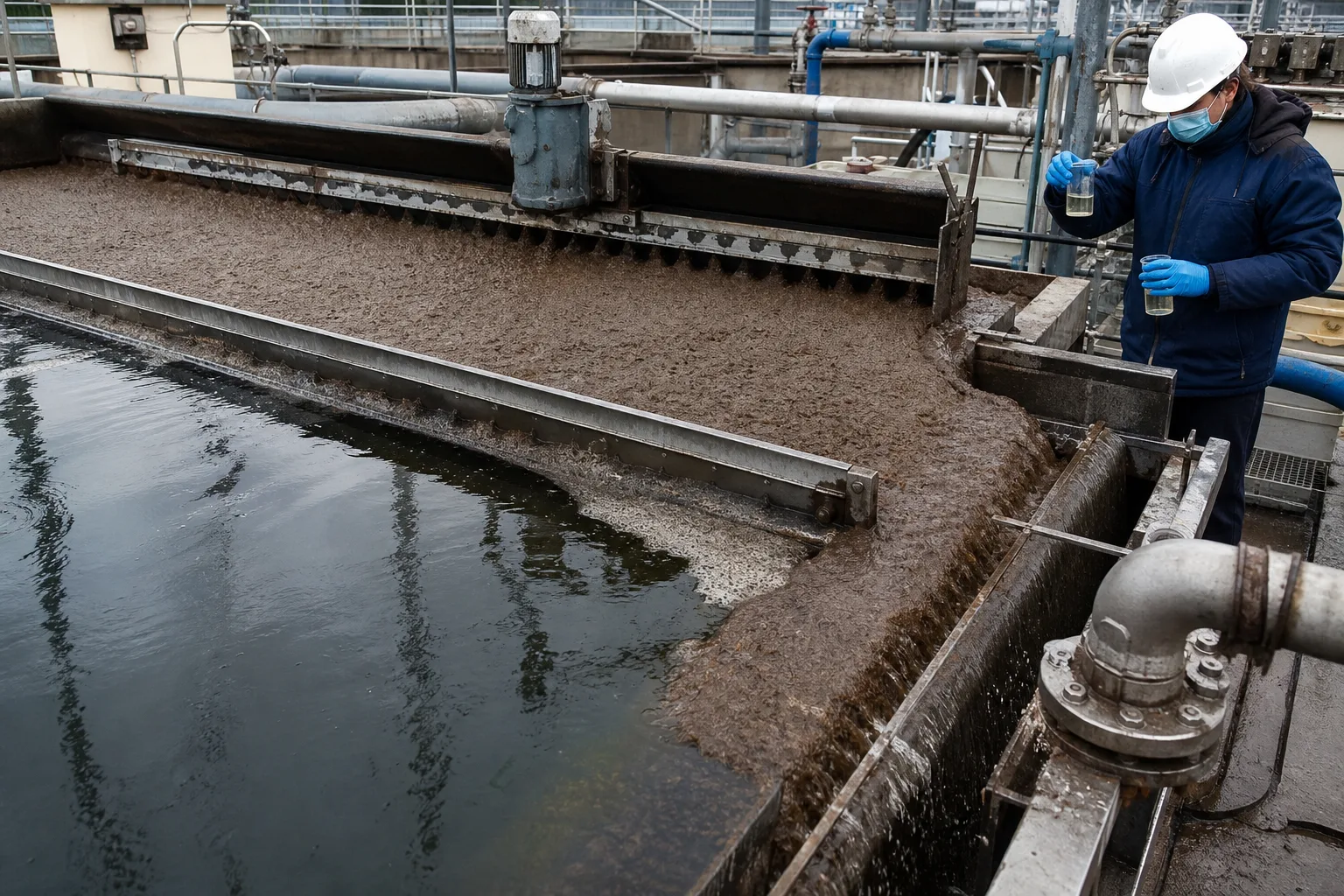 11Skimmer blade and track22Mature float layer33Float trough/discharge end44Clarified point samples
What to identify
- 1Skimmer blade and track
- 2Mature float layer
- 3Float trough/discharge end
- 4Clarified point samples
What the image proves
Thick float can mean slow skimming or blocked discharge, not high removal; thin watery float can mean excessive skimming. Poor effluent requires a combined bubble, chemistry, loading and skimmer diagnosis.
How to verify on site
Map float depth, water content, cracks and rollback; verify blade speed/travel/torque, trough level and discharge, while sampling feed, release, multiple effluent points and float with recycle pressure/flow.
Six steps from dissolved air to removed float
Separate saturation, release, attachment and skimming to locate lost performance.
1 Condition floc
Particles/oil + coagulation/flocculation
Create stable targets that collide with and hold bubbles.
2 Dissolve air
Clarified recycle + air + pressure
Dissolve air rather than carry large gas pockets.
3 Release pressure
Pressurized water → atmospheric whitewater
Nucleate fine, evenly distributed bubbles.
4 Attach
Microbubbles + floc/oil
Form bubble–solid complexes with lower mean density.
5 Float and clarify
Complexes ↑ / clear water ↓
Concentrate float at the surface and withdraw water below.
6 Skim and feed back
Float → collection/disposal
Use float and effluent to tune air, chemistry and loading.
Distinct duties of four DAF subsystems
Air, chemistry, hydraulics and skimming cannot replace one another.
Coagulation/flocculation
- Primary duty
- Create strong, bubble-receptive floc or oil aggregates
- Typical imbalance
- Unstable fines, weak/oversized floc, chemical excess or release breakage
- Field evidence
- Jar/DAF tests, size/strength, pH, mass dose and supernatant particles
Pressurized recycle
- Primary duty
- Reliably dissolve air into measured recycle and deliver it to release
- Typical imbalance
- Air ingestion/cavitation, pressure/level cycling, too little/much air or wrong recycle
- Field evidence
- Recycle flow, pump suction/discharge, saturator pressure/level, air flow and venting
Release and tank hydraulics
- Primary duty
- Make uniform bubbles and provide contact, rise and clarification space
- Typical imbalance
- Plugged/worn release, low drop, large bubbles, bias, short circuit or overload
- Field evidence
- Whitewater map, pressure drop, bubble appearance, point effluent and loading
Float removal
- Primary duty
- Control float depth/water and continuously remove separated solids
- Typical imbalance
- Fast/slow skim, worn blade, blocked trough, rollback or sinking
- Field evidence
- Float depth/solids, blade speed/torque, discharge, trough level and TSS
Use representative feed or sludge testing. Air solubility changes with pressure and temperature, while oil/surfactants, algae, salinity, floc properties and solids concentration change attachment and air demand. Do not transfer a fixed pressure, recycle ratio or dose between projects.
Align three operating evidence groups
Feed and floc
Flow, TSS/turbidity/oil or algae, temperature, pH; coagulant/PAM type and mass dose, feed points, floc size/strength and pre-DAF sample.
Air and recycle
Recycle flow/ratio, pump suction/discharge/current, saturator pressure/level, air flow, release pressure drop, whitewater distribution and pump/valve events.
Separation result
Clarified TSS/turbidity/particles/oil, float depth/solids/discharge, skimmer state, total hydraulic/solids loading, chemical and energy use.
How should deteriorating DAF performance be localized?
- Combined signal
- Whitewater weak/uneven; float thins and effluent TSS rises
- First suspicion
- Recycle pump, pressure/air, release plugging or low recycle flow
- Next action
- Verify measured recycle, pump pressures, saturator level/pressure and release drop; map whitewater and inspect releases
- Combined signal
- Whitewater strong but fine floc remains suspended or passes out
- First suspicion
- Poor destabilization/PAM, weak floc, large bubbles or release shear
- Next action
- Hold hydraulics and rerun combined coagulation–DAF tests; compare floc strength, bubble condition and particles before adding air
- Combined signal
- Float becomes very thick, locally sinks/rolls back and effluent cycles
- First suspicion
- Slow skimming, blocked trough/level, high solids load or excessive float residence
- Next action
- Shorten skim interval, inspect discharge, measure float solids/depth and verify feed solids loading
- Combined signal
- Pilot performs well but full scale fails only at high flow
- First suspicion
- Influent+recycle loading, contact/separation time or distribution exceeds full-scale capacity
- Next action
- Calculate total loading, sample effluent points, inspect flow pattern, calibrate flow and evaluate equalization/trains/recycle
Four common misconceptions
Larger bubbles give more useful buoyancy
Large bubbles provide less area per gas volume and brief contact. DAF relies on many microbubbles attaching to floc.
A whiter surface means higher removal
Whitewater proves bubbles exist, not that floc attaches or hydraulics separate it.
More pressure or recycle always fixes effluent
Both also change energy, release shear and total hydraulic loading; air-to-solids, bubbles, flow and float must be balanced.
DAF does not need coagulation
Some hydrophobic oil can float directly, but most fines, algae and emulsified oil need suitable chemical conditioning.