Illustrated guide · Industrial water systems
Why do ultrapure-water systems often combine UF, RO and EDI?
Start with particles, dissolved ions, weakly ionizable species and recontamination to see why UF, RO, EDI and the polish loop are complementary barriers—not progressively finer filters.
Direct answer
Direct answer
Ultrapure water requires simultaneous control of particles/colloids, dissolved salts, weakly ionizable silica or boron species, organics, dissolved gases, microbes and materials released by the system itself. UF, RO and EDI are often combined because their mechanisms and acceptable loads complement one another. Front-end UF screens suspended solids, colloids and some microorganisms, reducing turbidity and SDI to protect RO; it removes little dissolved salt. Pressure-driven RO uses a dense selective layer to separate most ions, silica, many organics and microorganisms into a concentrate stream, providing the main demineralization step; one or two passes depend on feed, recovery and weak-acid chemistry, and RO permeate is not automatically sterile. EDI normally polishes stable low-salt RO permeate: ion-exchange resin provides conductive transport, DC drives ions across selective membranes into concentrate chambers, and local H⁺/OH⁻ generation sustains resin function continuously. It cannot accept raw-water hardness, particles, oxidants or a high CO₂ load and does not replace RO. Microelectronics UPW may also require degassing, UV oxidation/disinfection, mixed beds, final UF, temperature control and continuous circulation; the sequence is not a universal recipe. Quality is multidimensional. A value near 18.2 MΩ·cm at 25°C indicates extremely low ionic contamination but does not certify TOC, particles, silica/boron, oxygen, microbes or metals. Stable operation depends on each outlet protecting the next barrier, correct concentrate/backwash disposal, shutdown sanitation, compatible materials and a continuously controlled distribution loop.
Four conditions make the barriers work as a train
Assign each contaminant form first, then define the feed contract for the next process.
UF separates particle risk from ion risk
UF removes suspended/colloidal matter but leaves most conductivity and dissolved salts. Turbidity, SDI and integrity protect RO but do not prove demineralization.
RO carries the main salt load and prepares EDI feed
RO produces permeate and concentrate. Scaling, chlorine oxidation, organic/biofouling and seal bypass still require control; a second pass is target-specific.
EDI polishes only stable, low-scaling, low-salt feed
Resin, ion-selective membranes and DC remove residual ions. Hardness, CO₂, silica, temperature, flow and current density must remain within design.
The polish loop must prevent recontamination
Very pure water can acquire ions, organics and microbes from air, materials, seals and stagnation. Degassing, UV, final UF, circulation and sanitation protect points of use.
A cleanroom train places UF, RO, EDI and sanitary circulation in load order
Large vertical modules form the particle barrier, horizontal pressure vessels perform RO demineralization, downstream EDI modules polish ions, and sanitary pipework/sampling carries product to the loop.
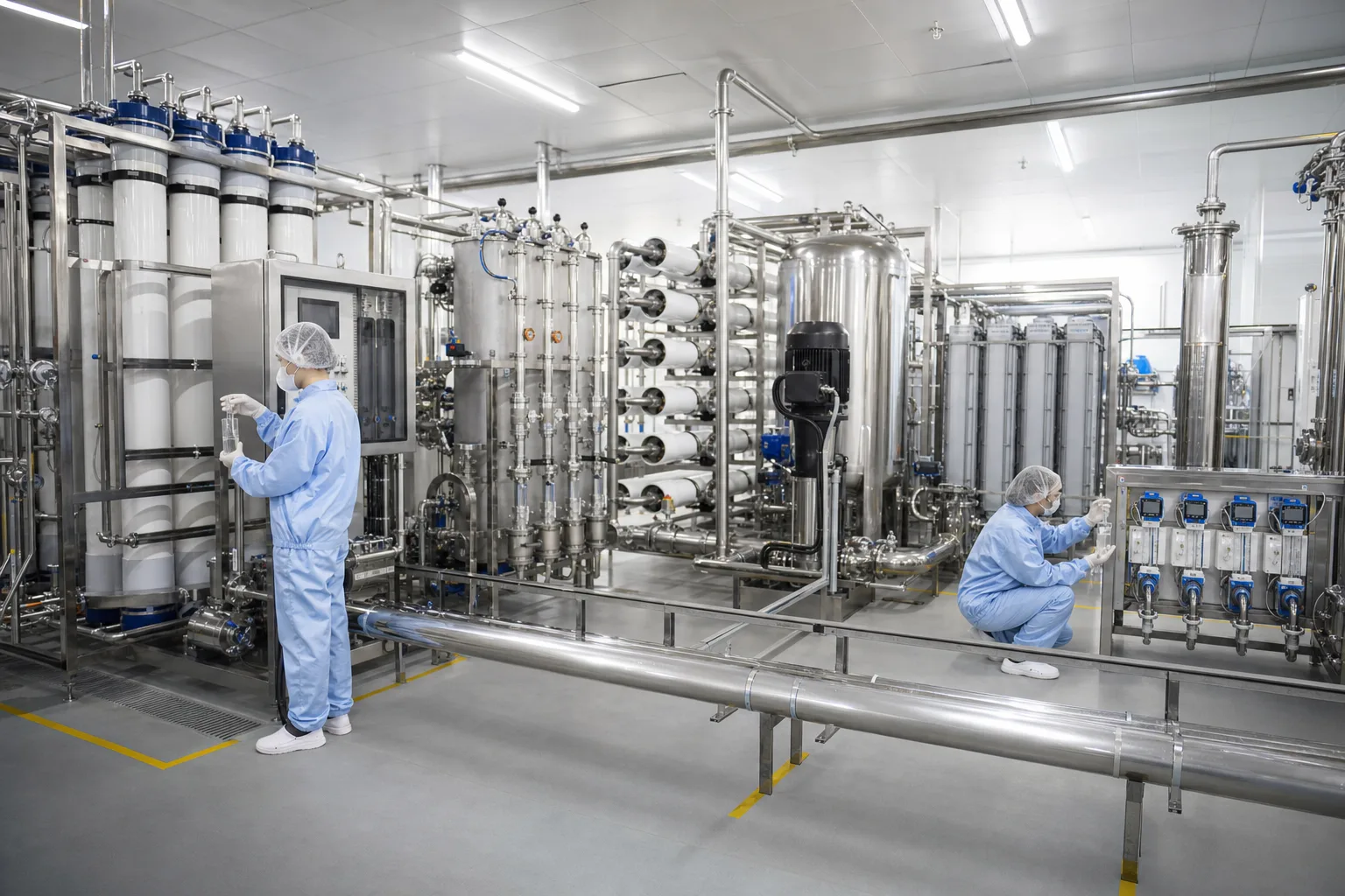 11UF rack: particles, colloids and SDI22RO vessels: main demineralization/concentrate33EDI modules: continuous RO-permeate polishing44Sanitary sampling, monitoring and loop piping
What to identify
- 1UF rack: particles, colloids and SDI
- 2RO vessels: main demineralization/concentrate
- 3EDI modules: continuous RO-permeate polishing
- 4Sanitary sampling, monitoring and loop piping
What this proves
The stages are not duplicates: UF protects RO, RO protects EDI, EDI raises resistivity, and the loop preserves quality to the tool.
Field check
Trace UF backwash/CIP, RO permeate/concentrate, EDI dilute/concentrate/electrode streams and loop return on the actual P&ID; verify sample identities and bypasses.
A bench model puts particle retention, RO separation, EDI migration and multiparameter analysis together
Particle feed and a retained membrane represent pretreatment; a clear pressure cell represents RO; an electrode cell represents EDI; vials and the analyzer compare stage-specific quality.
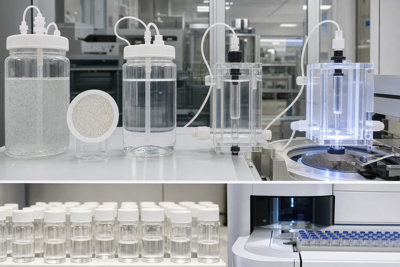 11Particle feed and UF retention disk22RO selective-layer pressure cell33EDI resin–membrane–electrode cell44Stage vials and ion/TOC/particle analysis
What to identify
- 1Particle feed and UF retention disk
- 2RO selective-layer pressure cell
- 3EDI resin–membrane–electrode cell
- 4Stage vials and ion/TOC/particle analysis
What this proves
All samples can look clear while differing by orders of magnitude. Neither eyesight nor resistivity alone distinguishes complete UPW quality.
Field check
Use one feed batch and controlled sample identity, P/T/flow/current; measure particles/SDI, conductivity/resistivity, TOC, silica/boron and required microbiology with calibrated methods.
A transparent skid shows the structural differences among UF fibers, RO elements, EDI stack and UV
A vertical fiber bundle screens particles, horizontal cylinders contain spiral RO elements, the black stack and DC cables form EDI, and the luminous reactor represents UV oxidation/disinfection.
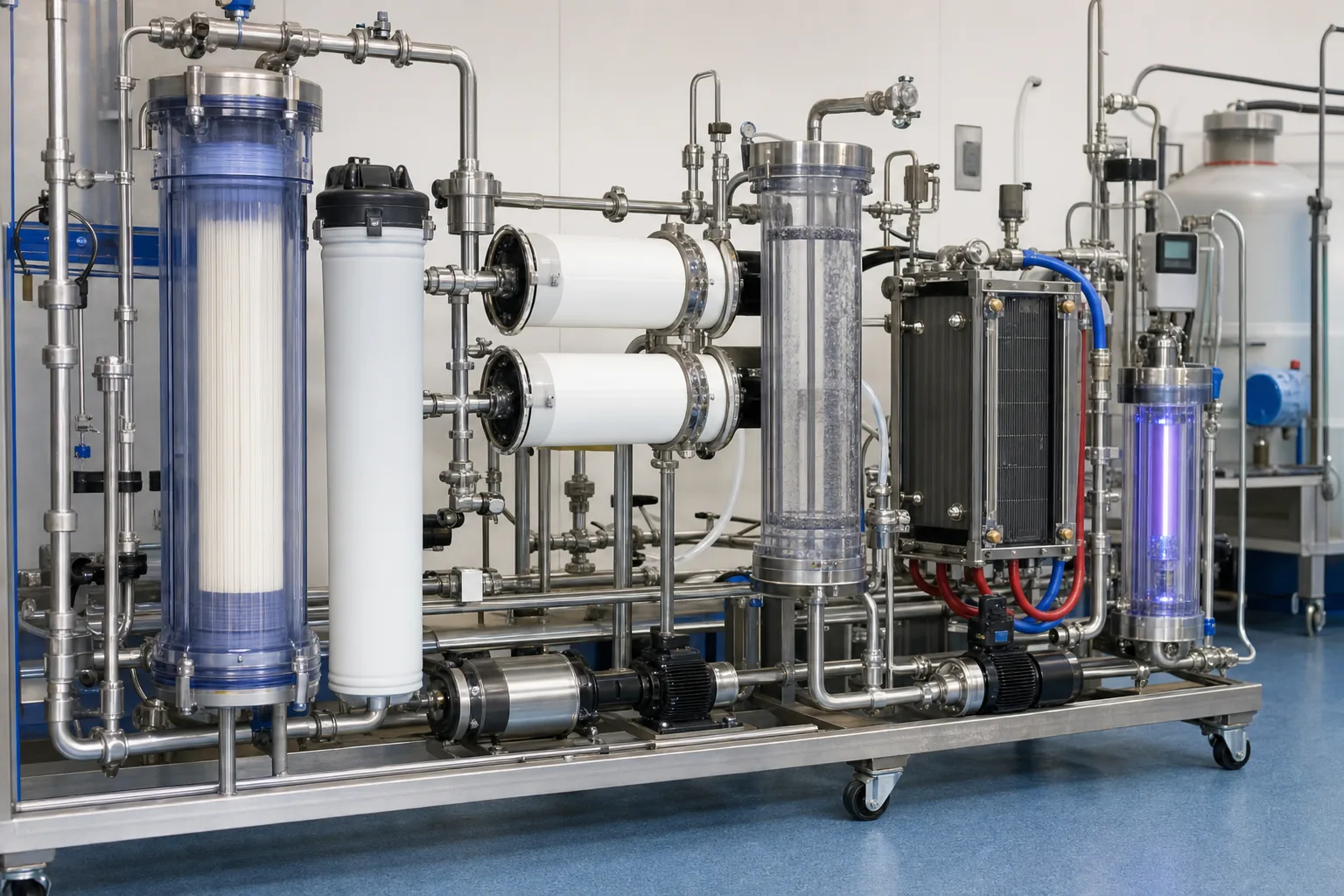 11Hollow-fiber UF bundle and shell22Spiral RO elements and pressure flow path33DC-powered EDI membrane stack44UV oxidation/disinfection polish reactor
What to identify
- 1Hollow-fiber UF bundle and shell
- 2Spiral RO elements and pressure flow path
- 3DC-powered EDI membrane stack
- 4UV oxidation/disinfection polish reactor
What this proves
Structure reveals mechanism: pores screen, the dense RO layer uses pressure, EDI transports ions with resin/membranes/field, and UV targets defined organic or biological risks.
Field check
Track UF integrity/TMP, normalized RO permeate/salt passage/stage DP, EDI voltage-current/flows/resistivity and UV intensity/hours/sleeve condition on a common temperature basis.
Four parallel modules, meters and samples assign a different acceptance contract to each stage
The foreground compares pretreatment feed, UF filtrate, RO permeate and EDI/final product under controlled flow and temperature.
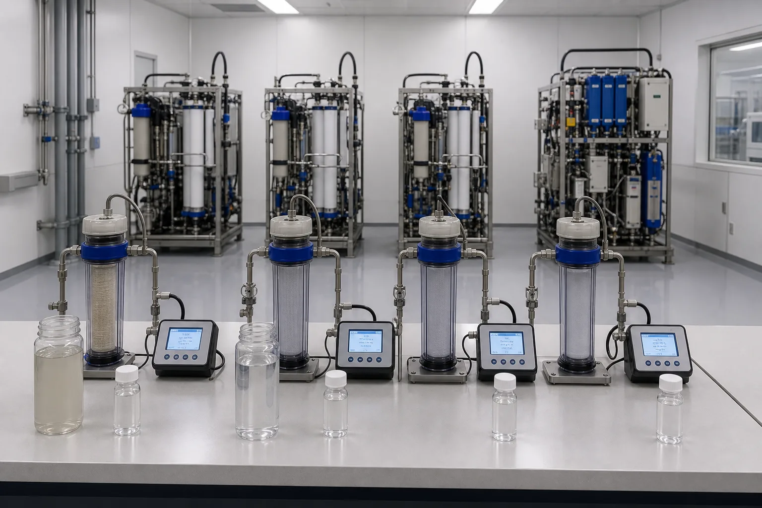 11Pretreatment feed: turbidity, hardness, TOC22UF outlet: particles, SDI and integrity33RO permeate: conductivity, salt, silica/TOC44EDI/final: resistivity and trace attributes
What to identify
- 1Pretreatment feed: turbidity, hardness, TOC
- 2UF outlet: particles, SDI and integrity
- 3RO permeate: conductivity, salt, silica/TOC
- 4EDI/final: resistivity and trace attributes
What this proves
Passing one stage means suitable feed for the next. UF does not certify ions, RO rejection does not certify all TOC/gas/particles, and EDI resistivity does not certify points of use.
Field check
Timestamp and temperature-correct all samples. When final quality changes, compare the closest adjacent points before jumping from raw water to final water.
A teardown table separates fouled UF media, RO sheet, EDI stack, final cartridges and samples
Technicians preserve component position and direction while meters and samples connect deposits to performance trends.
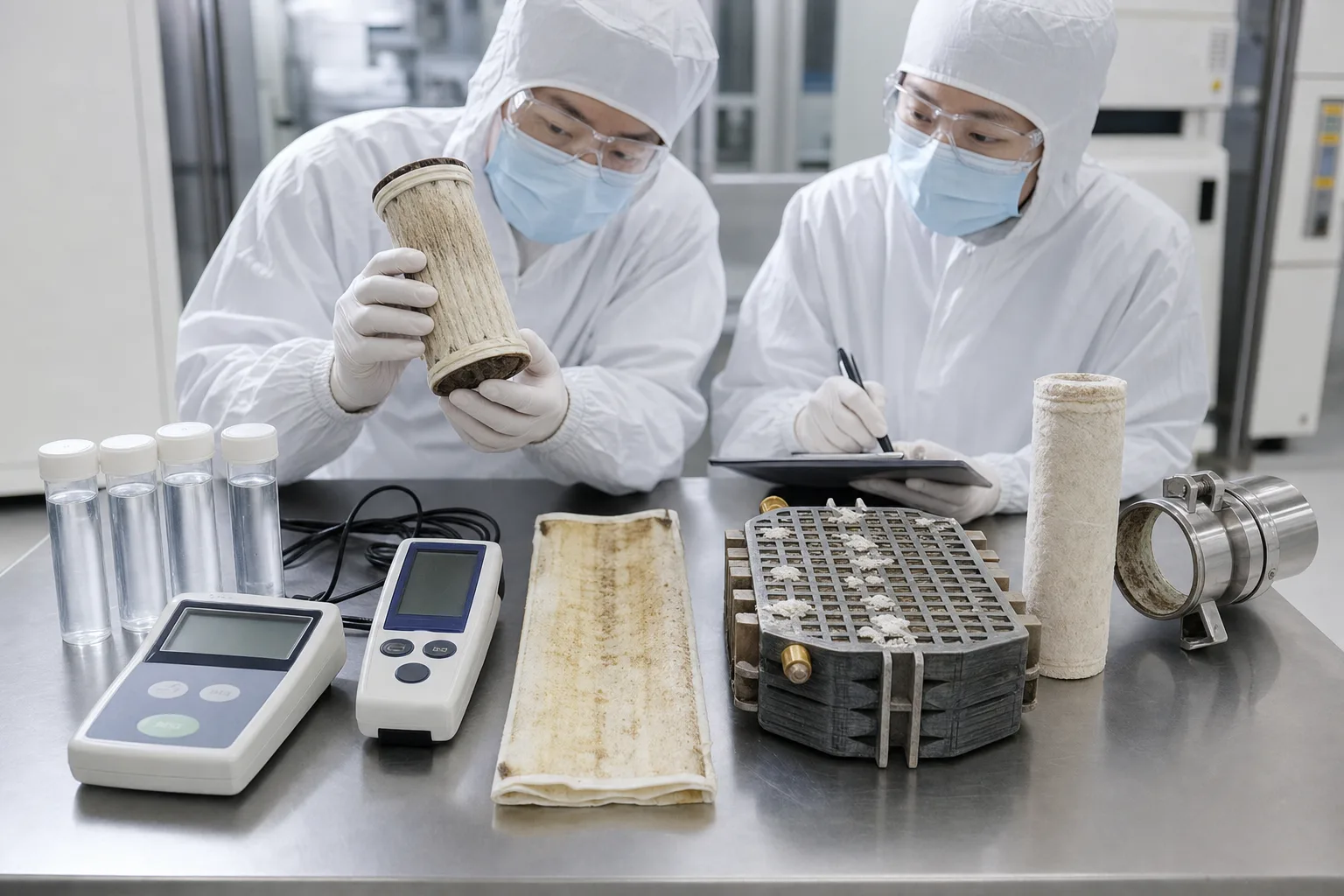 11Fouled UF/guard cartridge and end distribution22RO sheet deposit, damage or cleaning evidence33EDI stack flow path, membrane and scale44Stage samples, meters and final cartridge/housing
What to identify
- 1Fouled UF/guard cartridge and end distribution
- 2RO sheet deposit, damage or cleaning evidence
- 3EDI stack flow path, membrane and scale
- 4Stage samples, meters and final cartridge/housing
What this proves
Low final resistivity can originate in RO salt passage, CO₂ load, EDI power/flow/scale or loop contamination. Mixed dirty parts cannot locate it.
Field check
Preserve stage, position and flow direction; align TMP/DP/salt passage/current/temperature, perform suitable organic/element/mineral/microbial/integrity tests, then verify normalized recovery.
Nine steps from source to point of use
Contaminant load falls by stage while recontamination sensitivity rises.
1 Stabilize feed
Source/oxidant/hardness/organics → equalization, filtration, softening or dosing
Keep UF and RO feed within design.
2 UF barrier
Particles/colloids/microbes → retain + backwash/CIP waste
Lower SDI/turbidity and RO channel load.
3 First-pass RO
Pressurized feed → permeate + concentrate
Remove the major ionic, silica and organic load.
4 Interstage/second RO
First permeate → pH/degassing/second pass as needed
Address CO₂, weak-acid species and higher rejection targets.
5 EDI polish
Low-salt RO water + DC → high-resistivity dilute + concentrate
Continuously remove residual ions.
6 Tank and degas
Product → controlled gas/air interface
Limit CO₂/O₂ and environmental re-entry.
7 UV/resin/final UF
TOC/trace ions/particles/biological risk → targeted polish
Cover attributes outside the primary train.
8 Continuous loop
Sanitary supply → points of use → return
Control velocity, temperature, stagnation and sanitation.
9 Multiparameter release
Resistivity + TOC + particles + silica/boron/metals + biology
Certify water for the actual use.
Four barriers control different contaminant forms
Mechanism, waste stream and failure signal must remain distinct.
UF/particle pretreatment
- Primary role
- Retain suspended matter, colloids and some microbes for stable low-SDI RO feed
- Failure/boundary
- Fiber/seal bypass causes breakthrough; dissolved salts pass; fouling raises TMP
- Priority evidence
- Turbidity/particles/SDI, TMP/flux, integrity, backwash/CIP response and waste
RO demineralization
- Primary role
- Pressure-driven removal of most ions, silica, many organics and microbes
- Failure/boundary
- Scale/fouling/oxidation/seal bypass change normalized flow, passage and stage DP; concentrate remains
- Priority evidence
- Normalized permeate/passage, stage DP, conductivity/silica/TOC, mass balance and teardown
EDI ion polishing
- Primary role
- Resin transport, selective membranes and field continuously remove residual ions
- Failure/boundary
- Hardness/CO₂/silica, low flow, temperature or power mismatch impairs quality and causes scale
- Priority evidence
- Feed TEA/hardness/CO₂, dilute/concentrate/electrode flows, DC V/I, DP and ion trend
Polish/distribution
- Primary role
- Control TOC, gas, trace ions, particles and microbes and preserve point-of-use quality
- Failure/boundary
- Tank breathing, leachables, exhausted polish, dead legs/low flow or poor sanitation recontaminate
- Priority evidence
- Supply-return-POU spatial trends, TOC/particles/biology/metals/gas, velocity/T and sanitation
UPW specifications depend on application and facility standard. About 18.2 MΩ·cm at 25°C is the upper resistivity magnitude of extremely low-ion water, not a standalone UPW certificate and not proof of TOC, particle or microbial quality.
Keep four time-aligned stage records
Load and pretreatment
Source, T, turbidity, SDI, hardness/alkalinity, silica, TOC, oxidant, UF flow/TMP/backwash/integrity and upset events.
RO water-salt balance
Per-pass feed/permeate/concentrate flow/P/conductivity, normalized flow/passage, stage DP, recovery, silica/TOC and dosing/degassing.
EDI electric-water-ion balance
Feed conductivity/TEA/hardness/CO₂/silica, dilute/concentrate/electrode flow/DP, DC V/I/T and product resistivity/ions.
Polish loop and POU
Tank/vent, UV/resin/final-UF state, supply-return flow/T/P, resistivity, TOC, particles, silica/boron/metals, microbes and sanitation/shutdown.
Use the first changed attribute and adjacent sample pair
- Signal
- UF filtrate particles/SDI rise without high TMP
- Priority hypothesis
- Fiber integrity, seal/header bypass or sample contamination rather than ordinary reversible fouling
- Next step
- Run specified integrity testing and rack samples; inspect seals and sampling before stronger backwash
- Signal
- RO conductivity/salt passage rises with flow or stage-DP change
- Priority hypothesis
- Temperature/pressure, oxidation, scale/fouling or connector bypass separated by normalization and location
- Next step
- Normalize and validate mass balance, then profile by stage/element and combine cleaning response with integrity checks
- Signal
- RO permeate is stable but EDI resistivity falls with V/I or DP change
- Priority hypothesis
- CO₂/TEA/hardness/silica load, power, flow distribution or stack scale
- Next step
- Analyze complete EDI feed and ion balance, verify T/flow/DC/degassing, then follow OEM cleaning/repair decision
- Signal
- Primary product passes but return or remote POU TOC/particles/microbes/metals rise
- Priority hypothesis
- Tank/air interface, leachables, dead leg/low flow, exhausted polish or incomplete sanitation
- Next step
- Map supply-return-POU trends and inspect velocity/T/dead legs, UV/resin/final UF, welds/seals and sanitation coverage
Four common misconceptions
UF, RO and EDI are successively finer filters
UF screens particles, RO pressure-separates through a dense layer, and EDI transports ions with resin, membranes and DC.
Two-pass RO automatically makes UPW
TOC, particles, gases, microbes, metals and distribution recontamination still require independent control.
EDI can treat raw water directly
EDI is designed for stable low-salt RO permeate; hardness, particles, oxidants and CO₂ exceed its boundary.
18.2 resistivity means everything passes
Resistivity mainly reflects ions and depends on temperature/CO₂; trace attributes need separate methods.