Illustrated guide · Industrial water systems
Why does a cooling tower make circulating water saltier?
Follow heat-driven evaporation through makeup, drift, blowdown and leakage balances, then connect cycles of concentration with conductivity, scale, corrosion and aerosol control.
Direct answer
Direct answer
An open cooling tower rejects heat by evaporating a small fraction of its recirculating water. The vapor is mainly H₂O; calcium, magnesium, chloride, sulfate, silica and most other dissolved constituents do not leave in the same proportion. Level control replaces evaporated water with makeup that brings a new mineral load. Water therefore leaves while most salt remains and more salt enters, so circulating-water conductivity and conservative-ion concentration rise. Controlled blowdown removes concentrated liquid and makeup restores volume. Drift, leaks and overflow also remove liquid and salt, but they are losses to minimize rather than substitutes for controlled blowdown. At steady state M=E+B+D+L (makeup equals evaporation, blowdown, drift and other liquid loss). For a suitable nonvolatile, nonreactive tracer, cycles of concentration CoC≈Ccirculating/Cmakeup. If drift and leakage are small, CoC≈M/B and B≈E/(CoC−1). These are balance models, not universal chemistry: conductivity changes with temperature, treatment chemicals and makeup, while carbonate or silica may precipitate and cease to be conservative. Safe cycles therefore require ion chemistry, pH/alkalinity, temperature, treatment and equipment condition. Higher cycles can save water but raise scale, corrosion and biological-control difficulty; low cycles waste makeup, chemicals and discharge capacity. A visible white plume is mostly condensed water vapor, not proof of salt mist. Liquid drift droplets can carry dissolved chemicals and microorganisms and must be limited with drift eliminators, maintenance and a water-management program.
Four facts explain the rising salinity
Evaporation drives concentration, but heat load, makeup chemistry, liquid losses and control establish the final level.
Evaporation removes water while most dissolved salts stay
Warm water forms films over fill and contacts air. A fraction changes phase and removes latent heat. Common ions remain in the liquid; volatile species, gas exchange and chemical reactions need separate balances.
Every unit of makeup brings another mineral load
Level control maintains basin inventory; it does not know whether cycles are safe. A change in makeup hardness, alkalinity, chloride, sulfate, silica or conductivity requires review of blowdown and treatment limits.
Salt leaves with liquid, solids or chemical transformation
Blowdown is the controllable outlet. Drift, leaks and overflow carry salt but should be minimized. Scale only moves material from water onto equipment and adds thermal resistance.
The target is an optimized limit, not the highest cycle
Water savings must fit saturation, wall temperature, residence time, materials, biofilm control, treatment chemistry and discharge permits.
An open tower transfers process heat to air while evaporating a small water fraction
Distribution and fill expose hot water to air; the fan exhausts warm humid air, cooled water falls to the basin and pumps return it to the heat load. Makeup and blowdown close the basin balance.
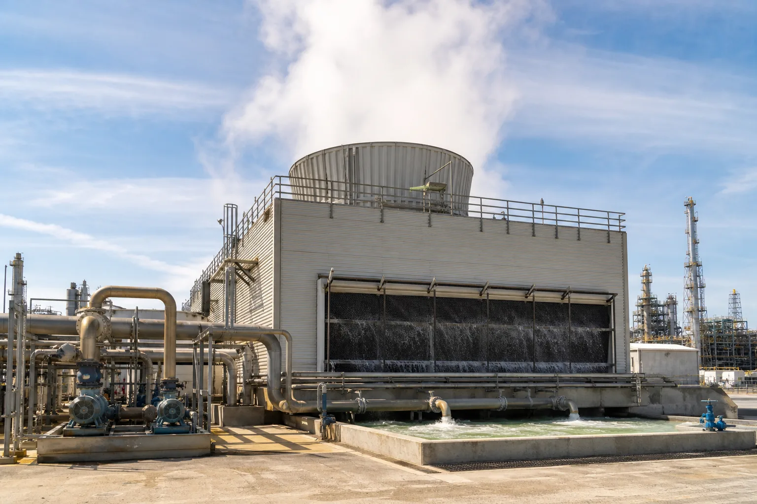 11Fan and humid exhaust plume22Air inlet, fill and falling-water zone33Circulation pumps and supply/return headers44Basin, makeup and blowdown boundary
What to identify
- 1Fan and humid exhaust plume
- 2Air inlet, fill and falling-water zone
- 3Circulation pumps and supply/return headers
- 4Basin, makeup and blowdown boundary
What this proves
The fan does not blow salt into the loop. Evaporation selectively removes water; the pump moves inventory, the level valve replaces loss and the blowdown valve provides the controlled salt outlet.
Field check
Trend makeup M, blowdown B, circulation, basin level, tower inlet/outlet temperature and wet bulb together. Account separately for leaks and overflow before assigning all makeup to evaporation.
Matched makeup, circulating and blowdown samples reveal concentration; color does not
Beakers and conductivity probes illustrate point sampling. Location, time, temperature compensation and calibration must be consistent; clarity is not salinity.
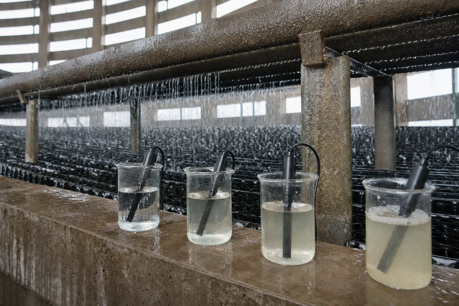 11Makeup baseline and conductivity22Lower-cycle sample33Higher-cycle sample44Blowdown sample and laboratory ions
What to identify
- 1Makeup baseline and conductivity
- 2Lower-cycle sample
- 3Higher-cycle sample
- 4Blowdown sample and laboratory ions
What this proves
Calculate cycles from a suitable tracer in samples from the same period. Conductivity is useful for continuous control, but it is not proof that every ion has concentrated equally.
Field check
Calibrate online and portable conductivity, verify temperature compensation and sample flow, clean fouled probes, and cross-check periodically with chloride or another conservative ion and a complete analysis.
A transparent rig puts spray, fill, airflow, basin and balance measurements in one system
Hot water sprays over fill, air crosses the wet area, cooled water reaches the basin, and makeup/blowdown meters and sample points close E, B, M and concentration balances.
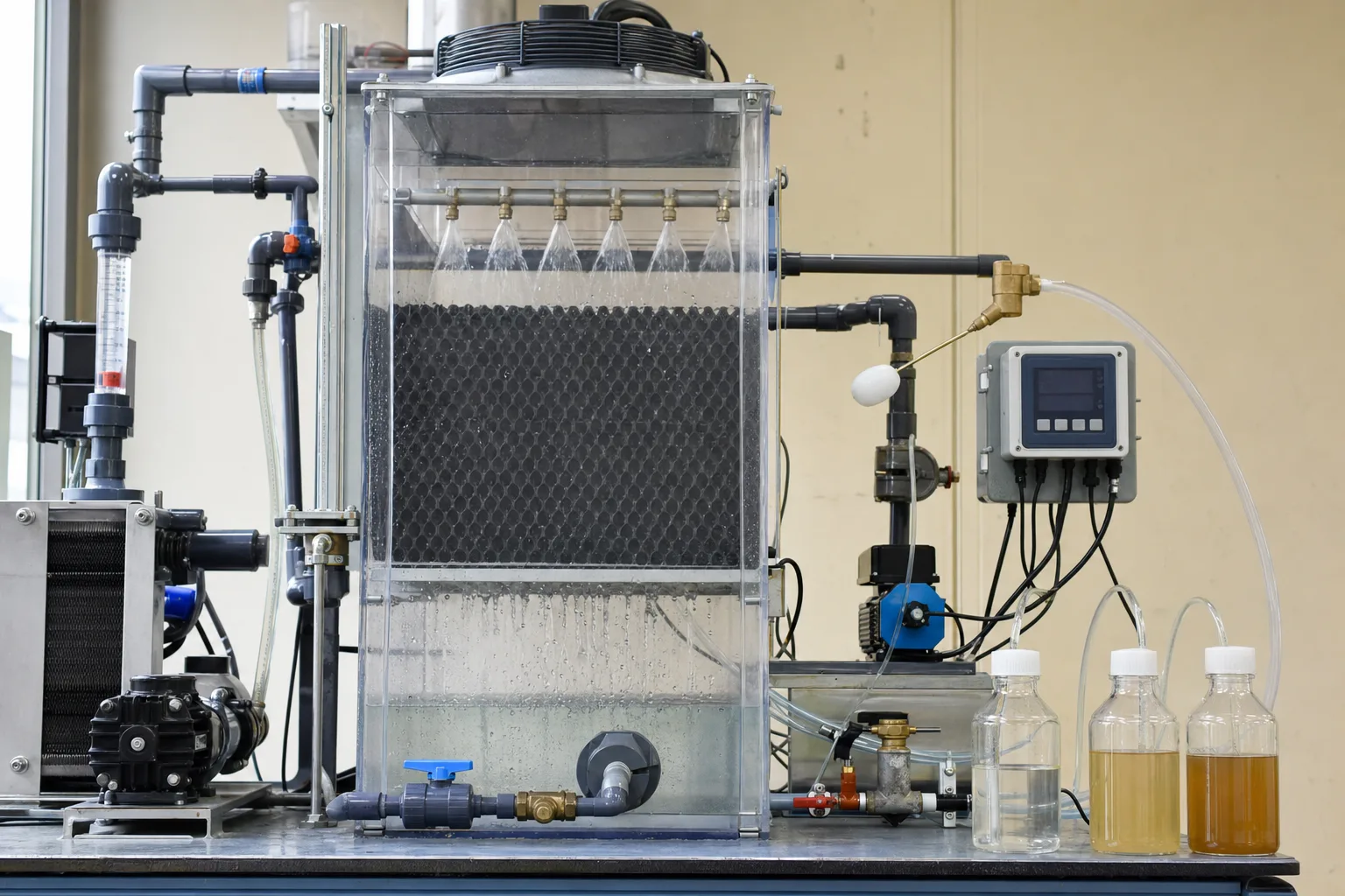 11Hot-water spray distribution22Wet fill heat and mass transfer33Fan airflow and drift eliminator44Cold basin, makeup/blowdown and instruments
What to identify
- 1Hot-water spray distribution
- 2Wet fill heat and mass transfer
- 3Fan airflow and drift eliminator
- 4Cold basin, makeup/blowdown and instruments
What this proves
Evaporation primarily follows heat load and ambient air state. Plume size alone cannot measure E; use heat or water balances and verify with the salt balance.
Field check
Record temperature range, circulation, fan state, wet bulb, makeup and blowdown over at least a day, correcting for basin inventory, overflow, side-stream filter backwash and sampling.
Matched-load tests show that lower blowdown saves water until chemistry turns concentration into scale
Left and center rigs represent controlled cycles; the right coil and basin show deposit accumulation. Only equal heat load, makeup, treatment and duration make the comparison causal.
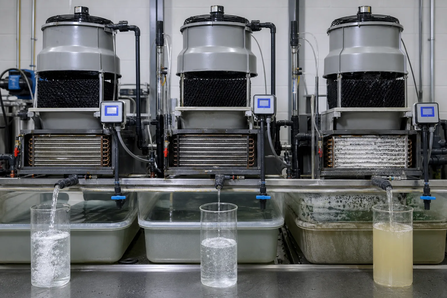 11Lower CoC: more blowdown, lower salts22Optimized CoC: water-risk balance33Excess/uncontrolled CoC: coil scale44Matched outlet and deposit evidence
What to identify
- 1Lower CoC: more blowdown, lower salts
- 2Optimized CoC: water-risk balance
- 3Excess/uncontrolled CoC: coil scale
- 4Matched outlet and deposit evidence
What this proves
Higher ion activity raises saturation risk, but scale also depends on pH, alkalinity, temperature, inhibitors, nucleation surfaces and residence time. High CoC alone is not a complete diagnosis.
Field check
At matched load compare cycles, pH, alkalinity, hardness, silica, chloride/sulfate, inhibitor residual, corrosion probes, exchanger approach temperature and deposit chemistry.
Field sampling, probe checks and deposit inspection connect salinity to equipment outcomes
Portable readings, bottle samples, visible mineral deposits and an opened bundle provide instrument, laboratory, location and equipment evidence.
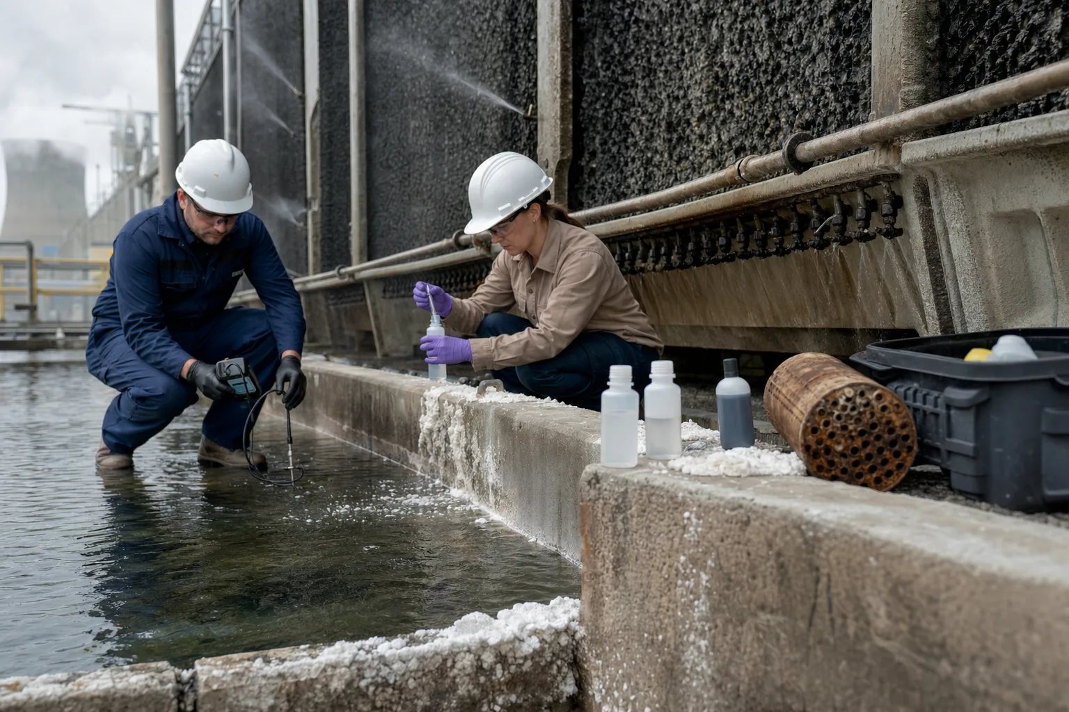 11Portable conductivity/pH cross-check22Makeup, circulating and blowdown samples33Basin/fill mineral deposits44Opened bundle and localized corrosion evidence
What to identify
- 1Portable conductivity/pH cross-check
- 2Makeup, circulating and blowdown samples
- 3Basin/fill mineral deposits
- 4Opened bundle and localized corrosion evidence
What this proves
A controller at setpoint proves only that one ionic signal is being controlled. It does not prove that surfaces are scale-free, materials are uncorroded or microorganisms are controlled.
Field check
Use fixed sampling points and frequencies; record makeup source, chemical lot, load, temperature and blowdown actions. Sample deposits before cleaning and apply isolation, LOTO, confined-space and exposure controls.
Seven steps: heat leaves while salts remain
Place energy, water and salts on one path so makeup, blowdown and plume are not confused.
1 Pick up heat
Cool water → exchanger/condenser → hot water
Carry process heat without materially changing salt inventory.
2 Distribute
Hot water → nozzles/troughs → wet fill
Create even area for air-water contact.
3 Evaporate
Small liquid fraction → vapor + air
Reject latent heat while most dissolved salts stay.
4 Remove drift
Humid air → eliminator → exhaust
Return entrained droplets and distinguish vapor from salty drift.
5 Reuse cold water
Fill drainage → basin → pump
Return cooled but more concentrated water to the load.
6 Add makeup
Fresh water M → basin
Replace E+B+D+L and introduce new dissolved minerals.
7 Blow down
Concentrated water B → discharge/reuse treatment
Remove salts within chemistry and permit limits.
Four subsystems manage heat, inventory, salts and risk
Changing one fan, level valve or blowdown valve does not prove the system is controlled.
Process exchanger and circulation
- Normal duty
- Carry heat to the tower at required flow and range
- Typical mismatch
- Process leak contaminates the loop, off-design flow/load, bypass or local high wall temperature
- Evidence
- Circulation Q, supply/return T/P, process tracers, exchanger approach and leak testing
Tower, distribution, fill, fan/eliminator
- Normal duty
- Provide uniform contact and retain drift droplets
- Typical mismatch
- Plugged nozzles, scaled/biofouled fill, low air, recirculation, damaged eliminator
- Evidence
- Range/approach, distribution, fan data, fill pressure/condition, drift and nearby deposits
Basin, makeup and level
- Normal duty
- Replace all loss and preserve pump submergence
- Typical mismatch
- Stuck valve, overflow, hidden leak, source change or meter drift
- Evidence
- Makeup total, level, valve, overflow/leak survey, complete makeup analysis and calibration
Blowdown, treatment and monitoring
- Normal duty
- Control scale, corrosion and microbes within safe cycles
- Typical mismatch
- Fouled probe, wrong temperature compensation/setpoint, blocked valve, failed feed or dead legs
- Evidence
- Actual B, conductivity/conservative ion, pH/alkalinity/hardness/silica, treatment residual, corrosion and microbial trends
The ideal steady balance is M=E+B+D+L. If D and L are small and the tracer is conservative, CoC≈M/B and B≈E/(CoC−1). Real audits must include drift, leaks, overflow, filter backwash, sampling, precipitation and basin inventory change.
Keep three evidence groups on the same timeline
Water and heat
Makeup/blowdown totals, basin level, leaks/overflow, circulation, supply/return temperature, wet bulb, fan/pump state and process load.
Makeup–circulating–blowdown chemistry
Temperature-compensated conductivity, pH, alkalinity, hardness, chloride/sulfate, silica, TDS, treatment residuals and required microbiological indicators.
Equipment and environmental results
Exchanger approach/pressure drop, corrosion coupons or probes, fill/nozzle/eliminator condition, deposit analysis, drift/nearby deposits, cleaning frequency and water-management actions.
Diagnose with M–B–conductivity–equipment results
- Signal
- Circulating conductivity rises, basin level is normal and measured blowdown is near zero
- Suspect first
- Probe/control never triggers, blowdown valve/line is blocked or isolated, or the setpoint is too high
- Next step
- Cross-check conductivity and temperature compensation, stroke the valve and measure real B; inspect logic, interlocks and discharge backpressure
- Signal
- Conductivity cycles look acceptable but exchanger scale or approach temperature worsens
- Suspect first
- Local heating, pH/alkalinity/hardness/silica saturation, low inhibitor, or a non-mineral deposit
- Next step
- Analyze full chemistry, residual and deposit; inspect location, velocity and wall temperature rather than changing one conductivity number blindly
- Signal
- Makeup rises and cycles fall without a matching heat-load increase
- Suspect first
- Excess blowdown, basin/piping leak, overflow, hunting level valve, filter backwash or unmetered use
- Next step
- Close a 24-hour M/B/level/side-loss balance, verify meters and find the water destination before raising cycles
- Signal
- A large white plume or nearby wet/salt spots appear
- Suspect first
- The plume may be vapor condensation; wet or salt deposits point more strongly to liquid drift and eliminator/distribution problems
- Next step
- Do not infer salt loss from visibility; inspect eliminators, fan and distribution, assess drift/aerosol exposure and implement water-management controls
Four common misconceptions
The white plume is salt fog
It is mainly condensed vapor. Salts travel in entrained liquid drift droplets.
The makeup valve controls cycles
It controls level. Blowdown, monitoring and chemistry limits control cycles.
Conductivity ratio is every ion's true cycle
It is a useful proxy affected by temperature, treatment, precipitation, gas exchange and makeup variation.
The highest cycles are always the best
Water savings diminish while scale, corrosion, microbial and discharge risks rise. The optimum is site-specific.