Illustrated series · Membranes & separation
Why can hollow-fiber UF membranes be backwashed?
Backwashing is not a feed pump running in reverse. Separate feed and filtrate passages in a hollow fiber let clean filtrate cross the wall backward, loosen reversible deposits on the feed side and carry them to waste. The five figures move from the full system to the fiber wall, cycle, recovery evidence and teardown diagnosis.
Short answer
Short answer
A hollow-fiber wall separates the feed side from the filtrate side, so the transmembrane pressure can be reversed. In a common outside-in module, filtration moves water from outside the fiber into the lumen while particles remain on the outer surface. Backwash sends clean filtrate from the lumen outward; reverse hydraulic drag, often assisted by air scour, removes loose deposits. It restores loss caused by reversible fouling, but it cannot repair broken fibers or replace chemical cleaning for scale, adsorbed organics or biological fouling.
Backwash works only when four conditions are met
Hollow-fiber modules do not all use the same flow direction or limits. Confirm the product boundary before programming the valve sequence.
Flow direction is known
Outside-in and inside-out modules place feed on different sides. Backwash must run from the filtrate side across the wall to the feed side; equipment appearance is not enough.
Backwash water is suitable
UF filtrate or other manufacturer-approved clean water is normally used so particles and microbes are not pushed into the pores from the clean side.
Valves and waste paths switch correctly
Filtration, filtrate, top/bottom waste and air valves must sequence so detached solids leave the module instead of settling again.
Pressure and air stay within limits
Backwash TMP, flow, air-scour intensity and duration are product-specific. Too little will not clean; too much can fatigue fibers, tangle them or create water hammer.
Start with the system: the feed pump does not run backward
This is a typical pressurized hollow-fiber UF rack. The vertical white modules are only the core; a filtrate/backwash tank, dedicated backwash pump, automatic valves, top and bottom waste headers and a residuals route make backwash possible.
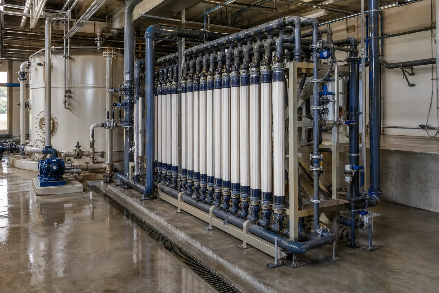 11Hollow-fiber modules22Filtrate/backwash tank33Backwash pump and line44Waste valve group
What to identify
- 1Hollow-fiber modules
- 2Filtrate/backwash tank
- 3Backwash pump and line
- 4Waste valve group
Key takeaway
An engineered backwash uses a dedicated clean-water source, pump and valve sequence to create reverse TMP from the filtrate side. The feed pump is normally stopped or isolated, not mechanically reversed.
How to verify on site
Trace the P&ID from the filtrate tank through the backwash pump, filtrate header and upper/lower waste outlets. Review the PLC sequence for any unintended feed-to-filtrate connection.
The mechanism is reversal of transmembrane pressure
At fiber scale, the lumen, porous wall and feed-side cake are visible. This outside-in example sends backwash water from the lumen through the wall and outward, pushing weakly attached particles away from the surface.
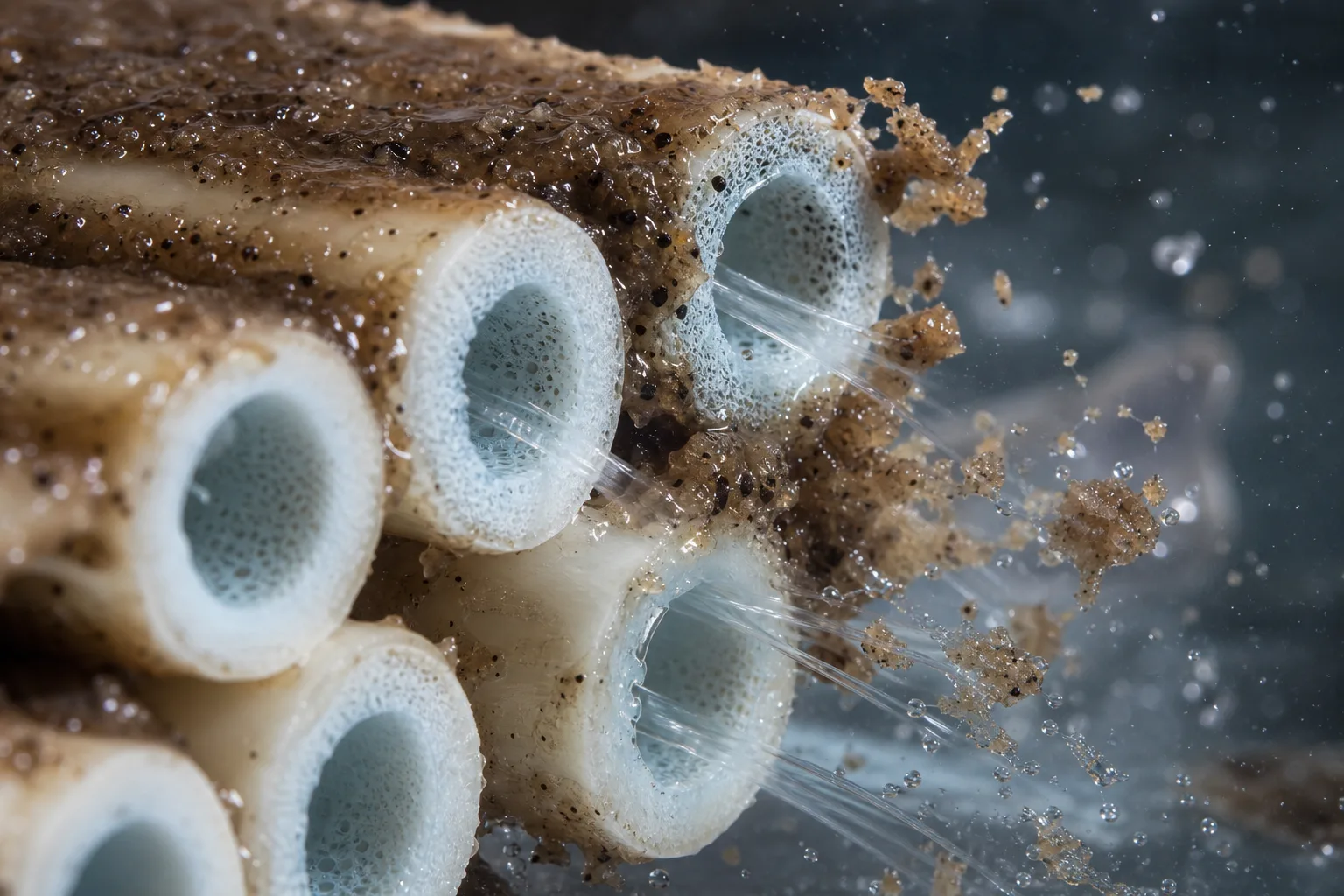 11Reversible cake layer22Fiber lumen33Porous membrane wall44Reverse hydraulic wash
What to identify
- 1Reversible cake layer
- 2Fiber lumen
- 3Porous membrane wall
- 4Reverse hydraulic wash
Key takeaway
The hollow geometry provides a separate clean-water passage from which force can be applied backward. It removes detachable surface deposits, not every contaminant lodged in pores or adsorbed to the polymer.
How to verify on site
Confirm outside-in versus inside-out service and the permitted filtration/backwash TMP and flow. If the sequence is correct but flow is low, check tank level, pump, check valve and flowmeter first.
A complete cycle is more than one reverse-water step
The transparent pilot module exposes the fiber bundle, accumulated solids and process connections. A common outside-in sequence combines filtration stop, air scour, drain, top/bottom backwash and forward flush; the exact order belongs to the selected product and project.
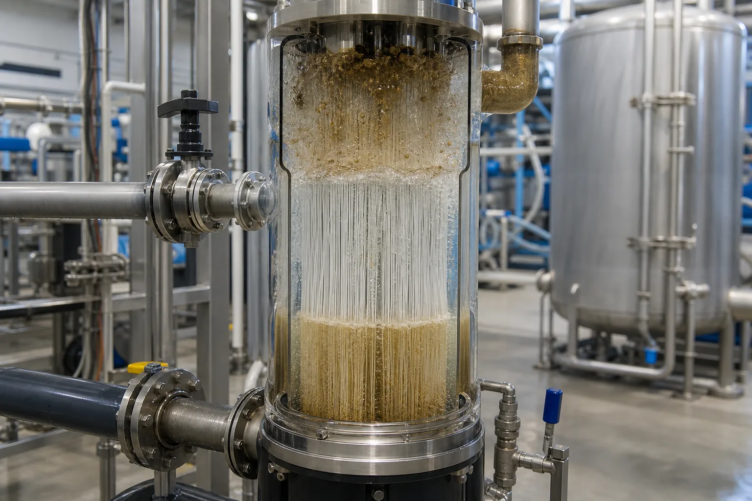 11Dislodged upper solids22Hollow-fiber bundle33Backwash-water inlet44Upper waste outlet
What to identify
- 1Dislodged upper solids
- 2Hollow-fiber bundle
- 3Backwash-water inlet
- 4Upper waste outlet
Key takeaway
Reverse water without loosening, draining and a final flush can leave detached solids inside the module. Effective cleaning closes the loop: loosen, transport, discharge and verify recovery.
How to verify on site
Step the valves and observe a clear pipe or waste sample. Air scour should release solids, top/bottom waste paths should drain freely, and initial post-flush water should go to the designed destination.
Judge effectiveness by recovery, not by a briefly clear sample
The three transparent modules show different outcomes: deposits remain at left, the center bundle is cleaner and orderly, and fibers at right are disorganized. Match appearance to before/after TMP, flux, normalized permeability and filtrate quality.
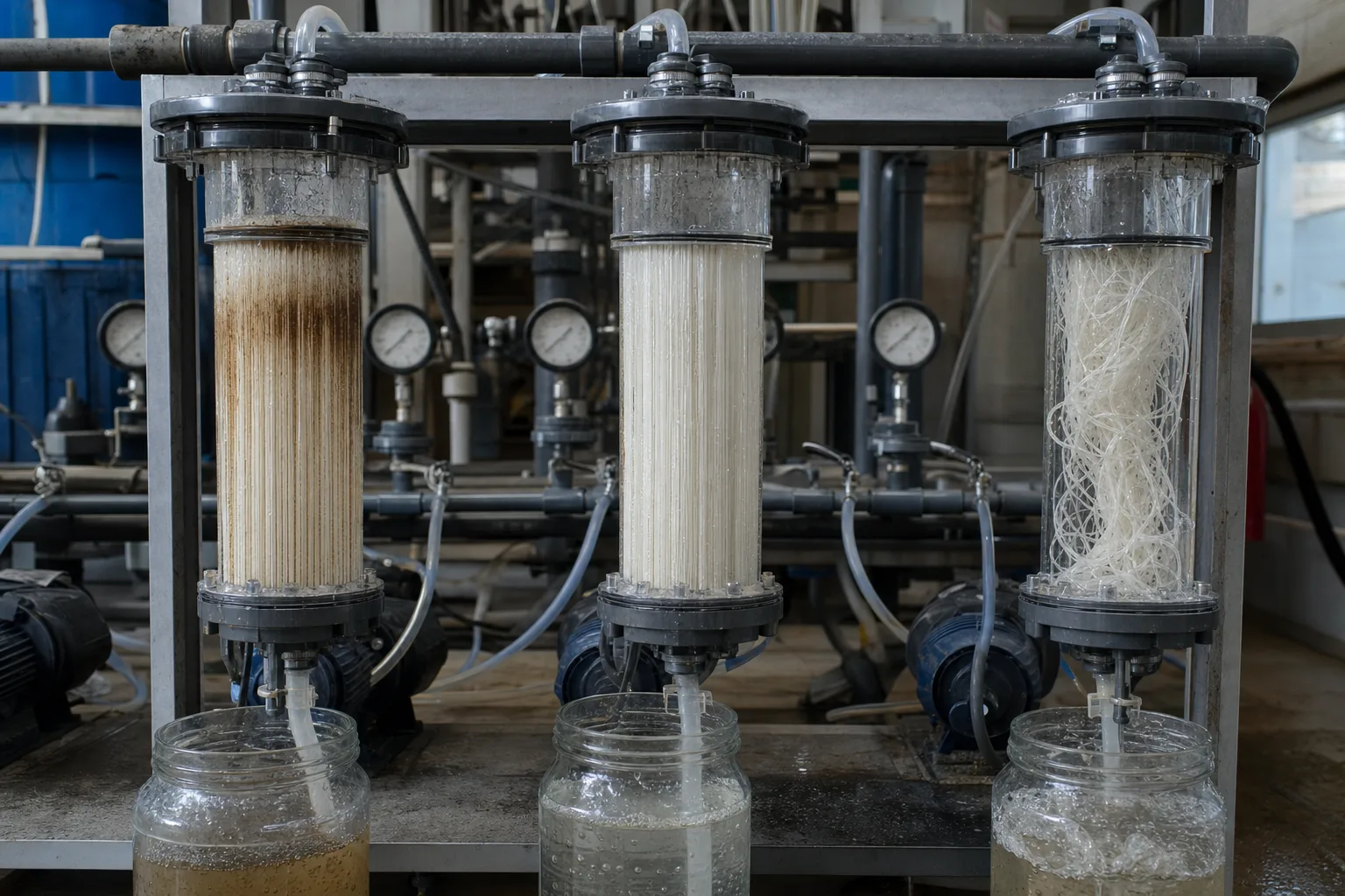 11Residual fouling22Recovered fiber bundle33Tangling or structural fault44Backwash waste sample
What to identify
- 1Residual fouling
- 2Recovered fiber bundle
- 3Tangling or structural fault
- 4Backwash waste sample
Key takeaway
A suitable backwash lowers the TMP required for the same production or restores normalized permeability without damaging fibers. Dirty waste is evidence of removal, but not the only acceptance measure.
How to verify on site
Compare data at similar temperature, flux and timing. Record TMP/permeability, backwash water use, waste turbidity and filtrate turbidity rather than judging one jar alone.
When backwash fails, separate fouling from loss of integrity
The teardown bench shows thick deposits, local blockage, exposed or broken fibers and water samples with different clarity. Physical backwash, CEB, CIP and fiber repair address different failure modes.
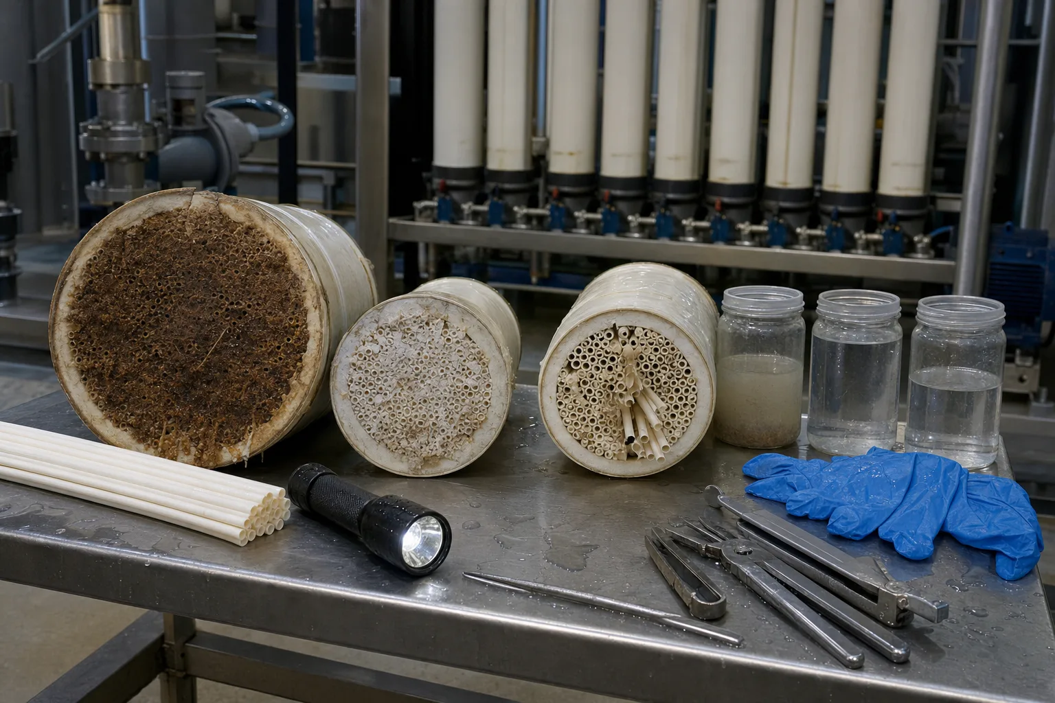 11Heavy deposit layer22Locally blocked module33Exposed/suspect fiber break44Feed, filtrate and waste samples
What to identify
- 1Heavy deposit layer
- 2Locally blocked module
- 3Exposed/suspect fiber break
- 4Feed, filtrate and waste samples
Key takeaway
If TMP remains high after backwash while filtrate quality stays normal, identify the foulant and escalate cleaning. If turbidity, particles or an integrity test are abnormal, investigate fibers, seals and valve bypass instead of increasing backwash force.
How to verify on site
Verify pressure, flow and turbidity instruments; then use a recovery trend, deposit analysis and a direct integrity test. Abnormal pressure decay or continuous bubbles calls for train isolation and module location.
Break one backwash into six actions
This is the logic of a common pressurized outside-in UF cycle, not a universal brand recipe. Actual valve positions, durations and set points must follow the installed module manual.
1 Filtration
Feed side → wall → filtrate side
Reversible deposits accumulate on the feed-side surface; at constant flow, TMP generally rises.
2 Stop/relax
Stop feed and isolate filtrate
Remove filtration force and create a stable state for air scour, drain and valve switching.
3 Air scour and drain
Bubbles rise on the feed side; dirty water exits
Loosen particles first, then discharge the high-solids liquid.
4 Backwash
Clean filtrate side → wall → feed side
Reverse flow strips surface cake and carries it toward upper/lower waste outlets.
5 Forward flush
Feed sweeps in the normal direction to waste
Remove residual solids and trapped air; divert initial water when the design requires it.
6 Return to service
Restore valves and produce filtrate
Compare TMP, normalized permeability and quality to prove that recovery occurred.
What backwash, CEB, CIP and integrity repair each solve
Escalate from evidence. Do not interpret every flux loss as insufficient backwash, and do not treat a filtrate-quality failure as ordinary fouling.
Routine physical backwash
- Main target
- Suspended solids, colloids and loose surface cake
- Trigger evidence
- TMP rises during a run and drops materially after backwash
- Next action
- Optimize frequency, flow, valve sequence, air scour and waste discharge
Chemically enhanced backwash
- Main target
- Organic, biological or inorganic deposits requiring chemical reaction
- Trigger evidence
- Physical-backwash recovery declines while integrity remains normal
- Next action
- Select chemical, strength and soak for the foulant and manufacturer limits
Offline CIP
- Main target
- Deep or accumulated fouling that CEB no longer restores
- Trigger evidence
- Sustainable flux falls or operating TMP/energy stays elevated
- Next action
- Identify the deposit, clean specifically and compare pre/post data
Integrity test and repair
- Main target
- Broken fiber, leaking seal or valve bypass
- Trigger evidence
- Filtrate turbidity/particles, pressure decay or continuous bubbles are abnormal
- Next action
- Isolate the train, locate the module/fiber, repair or replace, then retest
Permitted chemicals, pH, temperature, backwash TMP and air flow vary widely with membrane material, flow direction and module design. This page explains the decision logic; the product manual remains controlling.
Track at least three evidence groups
Recoverability
Compare pre/post TMP, normalized permeability and pressure at equal flux. Watch whether the recovery fraction declines from cycle to cycle.
Water balance and residuals
Account for filtrate production, backwash/flush water and waste solids. More frequent washing can improve surface condition while reducing net recovery.
Barrier integrity
Separate filtrate turbidity and particle counts from direct integrity testing. Normal hydraulic recovery does not prove that every fiber and seal is intact.
Three common mistakes
More pressure always cleans better
Intensity must stay inside module limits. Excess TMP, air, or a wrong valve sequence can fatigue or tangle fibers, create water hammer or damage seals.
All hollow fibers backwash inside-out
Backwash direction depends on filtration direction. Outside-in modules often backwash outward; inside-out modules do the opposite. Check the exact model.
Poor filtrate means stronger backwash
High TMP often suggests fouling or an operating set point. Poor quality may instead be a broken fiber, seal, bypass valve or instrument problem; separate performance from integrity first.