Illustrated series · Membranes and separation
How does EDI continuously produce high-purity water?
EDI stacks ion-exchange resin, cation- and anion-selective membranes, and a DC field in one module. Resin provides a fast path for trace ions, the field moves them into concentrate compartments, and water splitting at resin–membrane interfaces continually restores the resin's H⁺ and OH⁻ forms.
Direct answer
Direct answer
EDI is continuous because ion removal and electrical resin regeneration happen at the same time. RO permeate enters the dilute compartments; trace ions exchange onto mixed resin, migrate under DC through the corresponding ion-selective membrane, and leave in a continuously flowing concentrate stream. H⁺ and OH⁻ formed at resin–membrane interfaces restore exchange sites in place. EDI therefore avoids the offline acid/caustic regeneration cycle of a conventional mixed bed, but it still needs qualified RO feed, matched current, correct dilute/concentrate flows, and scale control.
Four conditions make “continuous” possible
EDI is a low-salinity polishing process, not an electric substitute for upstream RO.
RO removes the bulk load first
EDI expects low-conductivity feed with very low hardness, particles, organics, and oxidants. Excess silica, CO₂, hardness, or TOC can overload, foul, scale, or damage the module.
Resin forms a conductive path
Mixed cation and anion resin in the dilute cell exchanges trace ions and provides a much more conductive surface path than high-purity water alone.
Selective membranes control direction
Cation membranes pass cations to one concentrate cell; anion membranes pass anions to the other. Alternating cells keep those ions from readily returning to product water.
DC drives transport and regeneration
The field moves impurity ions and promotes limited water splitting at resin–membrane interfaces, supplying H⁺ and OH⁻ that restore resin sites. Current must match flow and ionic load.
Start with the train: EDI is the electrically driven polisher after RO
Plate-and-frame EDI modules are installed in parallel, with an RO rack behind them, a DC power/control cabinet to the right, and headers for dilute, concentrate, and flush streams.
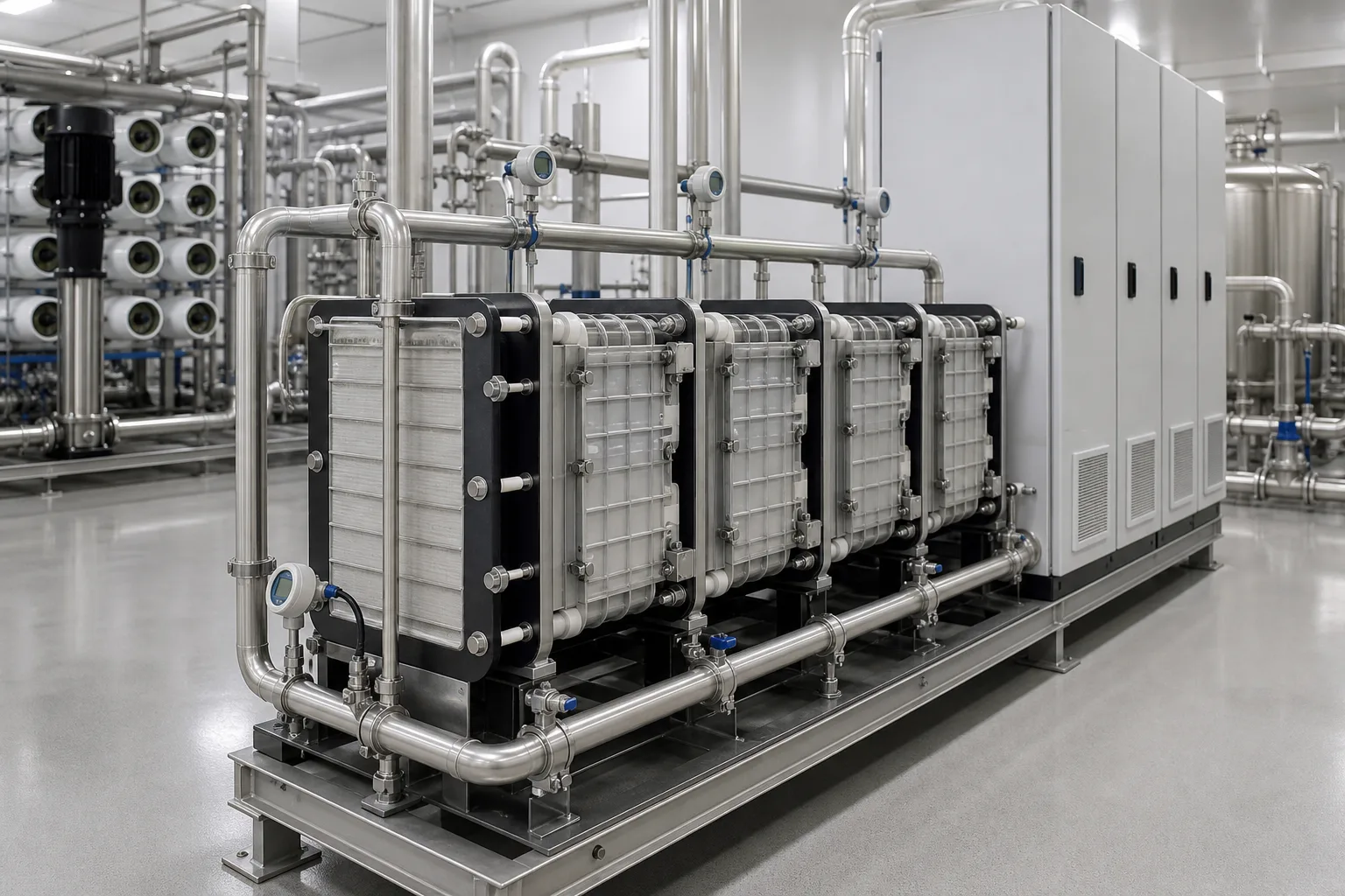 11EDI module stack22Upstream RO rack33DC power and controls44Dilute/concentrate headers
What to identify
- 1EDI module stack
- 2Upstream RO rack
- 3DC power and controls
- 4Dilute/concentrate headers
What the image proves
Continuous high-purity water is a train result: RO removes most ions, EDI polishes traces, and concentrate/electrode flush streams carry transferred ions and gases away.
How to verify on site
Trace RO permeate into EDI and keep product and concentrate connections distinct. Check polarity, flow, pressure, voltage, current, and product resistivity for each train.
Resin is a transport highway, not the final storage point
The enlarged dilute cell contains mixed cation and anion resin between two selective interfaces. Colored spheres represent trace ions exchanging onto resin and migrating toward opposite sides under DC.
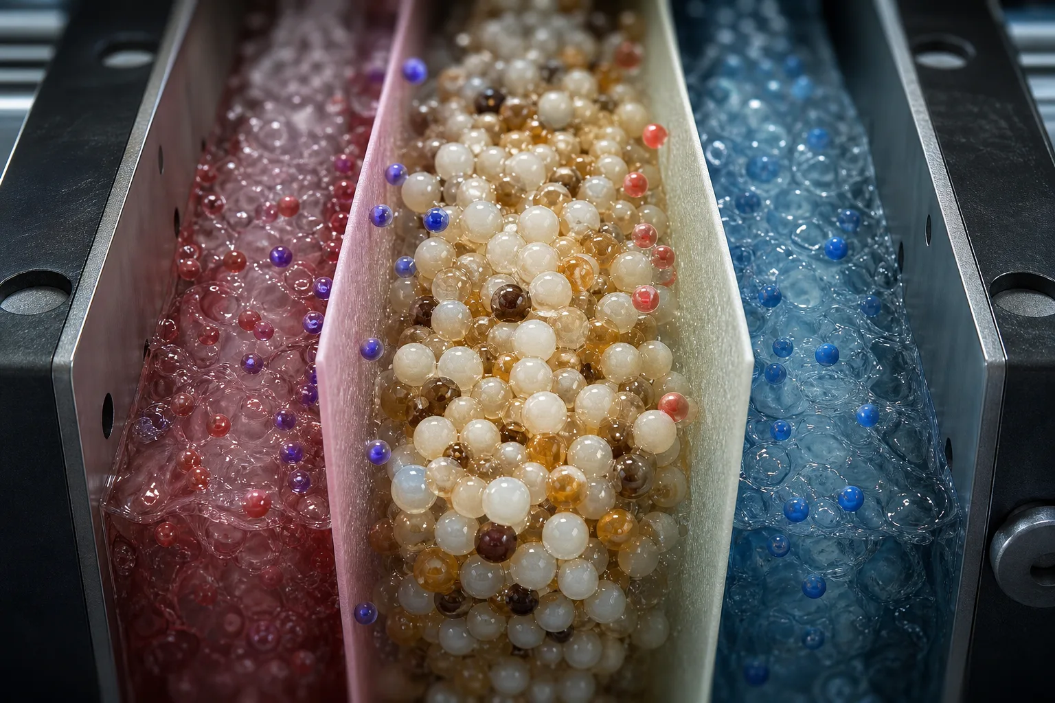 11Mixed resin in dilute cell22Anion-selective interface33Cation-selective interface44Migrating trace ions
What to identify
- 1Mixed resin in dilute cell
- 2Anion-selective interface
- 3Cation-selective interface
- 4Migrating trace ions
What the image proves
Resin concentrates trace ions onto conductive sites; selective membranes then move each charge into an adjacent concentrate cell. The resin accelerates low-salt transport instead of acting as a finite stand-alone cartridge.
How to verify on site
Trend product resistivity with current, feed load, and temperature. Extra resin or higher voltage alone cannot create EDI without the correct membrane interfaces and hydraulic path.
Alternating cells deliver product and salt-bearing concentrate together
The transparent stack reveals alternating dilute and concentrate cells, resin-filled channels, selective membranes, end electrodes, and bottom manifolds that distribute and collect the streams.
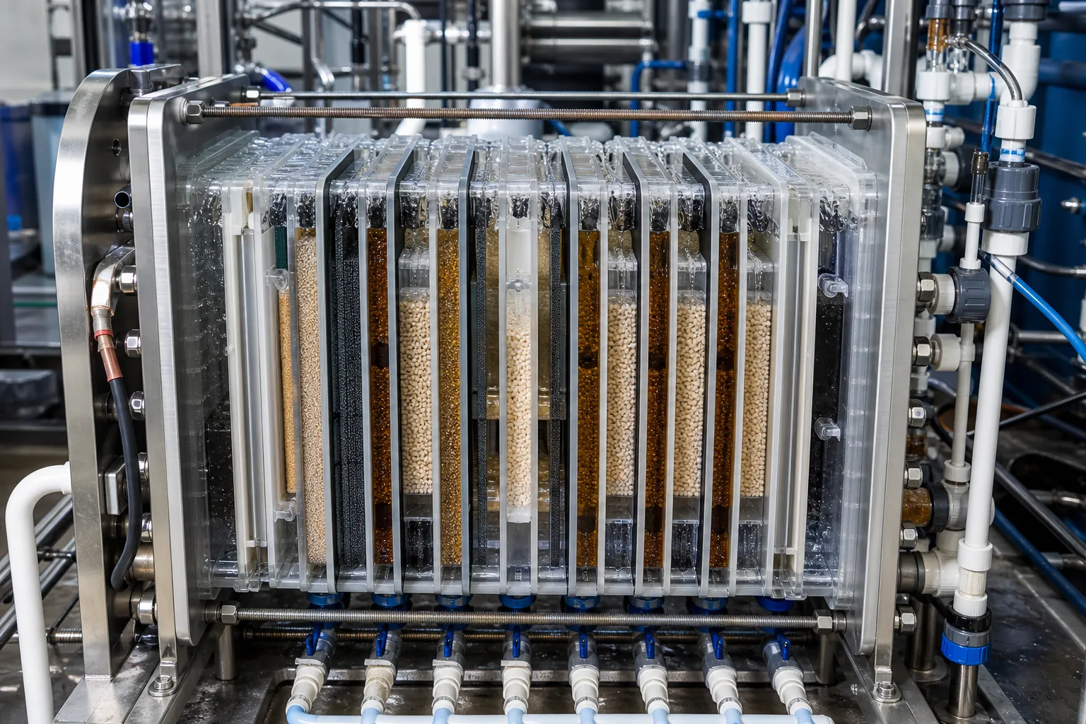 11Alternating dilute/concentrate cells22Resin-filled channels33End electrode and compression plate44Inlet/outlet manifolds
What to identify
- 1Alternating dilute/concentrate cells
- 2Resin-filled channels
- 3End electrode and compression plate
- 4Inlet/outlet manifolds
What the image proves
EDI does not store salt in the stack. Dilute cells continuously lose ions and make product; concentrate cells receive those ions and discharge concentrate. Continuous salt removal completes the regeneration loop.
How to verify on site
Verify dilute, concentrate, and electrode-flush flows and pressure drops. Prevent throttled outlets, reverse flow, or gas accumulation, and follow the module-specific pressure relationship.
When purity falls, compare electrical and hydraulic loading
Three test units represent excessive ion load or inadequate current, a balanced condition, and concentrate-side deposition or blockage. Sample appearance is only a clue; resistivity, flow, pressure drop, voltage, and current decide the diagnosis.
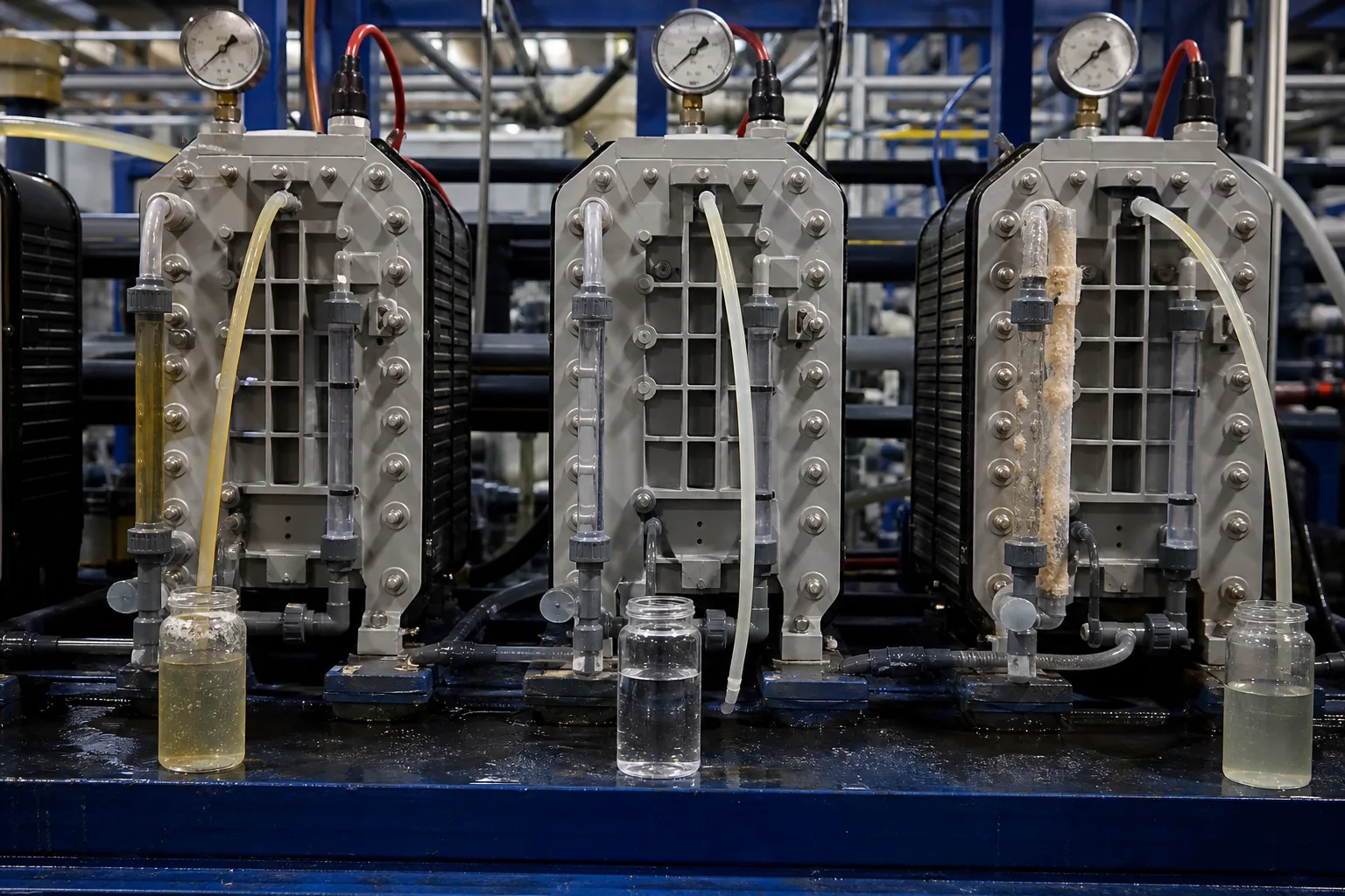 11High load/low current22Matched current and flow33Concentrate scale/blockage44Three product samples
What to identify
- 1High load/low current
- 2Matched current and flow
- 3Concentrate scale/blockage
- 4Three product samples
What the image proves
Feed load, temperature, flow, recovery, and DC setting can produce ion leakage, stable polishing, or concentrate scaling in the same module. Clear water does not prove deionization.
How to verify on site
Compare temperature-compensated resistivity and record feed conductivity/FCE, CO₂, hardness, silica, current density, dilute/concentrate flow, pressure drop, and recovery.
At teardown, separate scale, fouling, flow-path, and electrical faults
The opened stack shows pale mineral deposits, dark organic or metal fouling, seals and distribution plates, plus a meter and samples for electrical and water-quality checks.
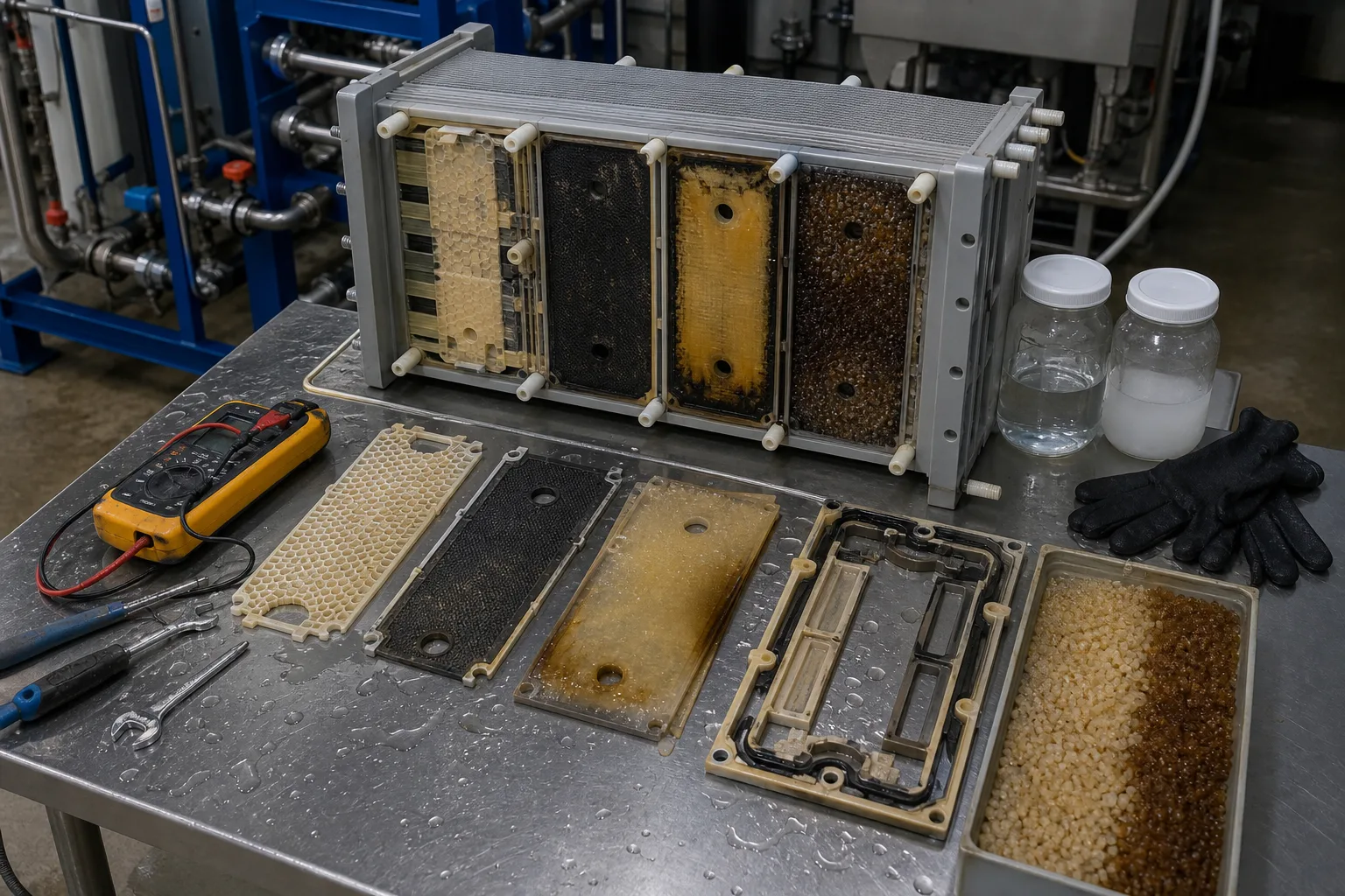 11Mineral scale/resin agglomeration22Dark organic/metal deposit33Seals and distribution path44Electrical checks and samples
What to identify
- 1Mineral scale/resin agglomeration
- 2Dark organic/metal deposit
- 3Seals and distribution path
- 4Electrical checks and samples
What the image proves
Hard scale points to hardness, silica, or recovery; dark deposits suggest organics, metals, or biology; dry zones and cross-flow implicate sealing or distribution; abnormal current also requires power, polarity, and connection checks.
How to verify on site
Preserve operating trends and feed analyses before a safe depressurized teardown. Map deposit location, sample resin/scale, test continuity, and clean or replace only under the module procedure.
Follow one impurity ion through six steps
This is the general path in a plate-and-frame CEDI stack. Module manuals govern actual flow direction, concentrate recycle, electrode flush, and settings.
1 Low-salt feed
RO permeate → dilute cell
Reduce salt, hardness, particulate, and organic loads to the module's feed window.
2 Resin exchange
Dissolved ion ⇄ resin site
Move trace cations and anions onto a continuous conductive resin surface.
3 Field migration
Cations → cathode; anions → anode
DC drives the two charge classes along resin and aqueous paths.
4 Selective crossing
Resin → selective membrane → concentrate
Pass the matching charge while limiting its return to the dilute cell.
5 Water-splitting regeneration
H₂O → H⁺ + OH⁻
Continuously restore cation and anion exchange forms at interfaces.
6 Two continuous outlets
Dilute → product; concentrate → reject/recycle
Make high-purity product while removing transferred ions and electrode products.
What do resin, membranes, the field, and the streams each do?
Separating the four roles explains both continuity and failure.
Ion-exchange resin
- Primary role
- Capture trace ions and form conductive transport paths in low-salt water
- What fails
- Fouling, clumping, or lost bead contact prevents useful ion transport
- Evidence
- Product resistivity, pressure drop, resin appearance, feed particles/TOC/metals
Cation/anion membranes
- Primary role
- Pass the matching charge into adjacent concentrate cells and limit remixing
- What fails
- Damage, fouling, or wrong assembly creates leakage, cross-flow, or local resistance
- Evidence
- Branch resistivity, membrane deposits, cell location, assembly and integrity
DC field
- Primary role
- Drive migration and form H⁺/OH⁻ that sustains in-place resin regeneration
- What fails
- Too little current leaves ions; excessive setting cannot rescue out-of-spec feed
- Evidence
- Voltage, current, polarity, temperature, feed load, vendor prediction
Dilute/concentrate/electrode flows
- Primary role
- Deliver product, remove ions and electrode products, and control concentration
- What fails
- Low flow, reverse flow, wrong pressure, or excessive recovery promotes scale, gas, and cross-flow
- Evidence
- Flow, pressure/drop, recovery, venting, concentrate analysis
EDI removes the periodic acid/caustic regeneration cycle, not concentrate, cleaning, or every downstream polishing need. Final degassing, polishing, sanitization, and loop control depend on the use-point specification.
Stable operation needs three evidence sets
Feed ionic and fouling load
Trend conductivity/FCE, CO₂, hardness, silica, TOC, oxidants, and particles. Falling product quality can originate in RO leakage or upstream degassing/chemical control.
Dilute, concentrate, and pressure balance
Verify each flow, inlet/outlet pressure, pressure drop, and recovery. Low concentrate flow or excessive recovery amplifies scaling and gas accumulation first.
Voltage, current, and product resistivity
Put electrical values, temperature-compensated resistivity, and feed load on one trend. Voltage alone and visually clear samples do not prove ion removal.
Route four common signals this way
- Signal
- Product resistivity falls with little pressure-drop change
- First suspects
- RO salt leakage, higher CO₂/ammonia load, excess flow, insufficient current, temperature or meter compensation
- Response order
- Retest feed/product and calibrate the meter, then compare load, flow, and current with the design
- Signal
- Module pressure drop keeps rising
- First suspects
- Particle plugging, resin agglomeration, concentrate scale, or flow-distribution fault
- Response order
- Reduce risk, map branch flow/pressure and feed filtration, then clean or inspect by deposit type
- Signal
- Voltage/current relationship changes or fluctuates abruptly
- First suspects
- Power, wiring, polarity, trapped gas, dry zone, high-resistance scale, or internal cross-flow
- Response order
- Perform electrical and venting safety checks first; verify stream pressures and branches before increasing voltage
- Signal
- Cloudy/crystalline concentrate or product-concentrate cross-flow
- First suspects
- Hardness/silica or recovery exceedance, low concentrate flow, seal or distribution-plate damage
- Response order
- Isolate the module, verify water quality/recovery, inspect sealing and flow paths, identify scale before treatment
Four common misconceptions
EDI can replace RO
EDI polishes trace ions in low-salt water. Without qualified RO pretreatment, ionic, hardness, and fouling loads quickly exceed its window.
Electricity destroys the salt
Impurity ions are mainly transferred into concentrate and carried away. Water splitting supplies H⁺/OH⁻ for resin regeneration.
More current always means better water
Current must match flow, temperature, and ion load. Excess raises energy, heat, and electrode-gas risk and cannot fix bad feed.
No chemical regeneration means no maintenance or waste
EDI still has concentrate/electrode flush and can scale, foul, leak, or need cleaning. It eliminates periodic resin acid/caustic regeneration.