Illustrated guide · Industrial water systems
How do boiler blowdown control and condensate recovery save water and energy?
Use water, impurity and enthalpy balances to see why blowdown is necessary but should not be excessive, and how clean hot condensate, flash steam and blowdown heat can return value safely.
Direct answer
Direct answer
Blowdown and condensate recovery solve different parts of the same balance. Blowdown removes nonvolatile salts, treatment residuals and sludge that steam cannot carry out reliably; condensate recovery returns the hot, usually low-hardness water formed after steam has delivered its latent heat. Too little blowdown allows TDS, silica, alkalinity or suspended matter to exceed limits and cause deposits, foaming or steam carryover. Too much discards hot treated water and chemicals. Control continuous surface blowdown from representative boiler-water conductivity cross-checked against silica, alkalinity, chloride or the program limiter; bottom blowdown is a short sludge-removal duty, not a substitute for continuous-flow control. When hot pressurized continuous blowdown enters a lower-pressure flash vessel, part becomes low-pressure flash steam because the saturation enthalpy changes. That steam may serve a deaerator or compatible low-pressure load; the remaining concentrated hot liquid can preheat makeup through a heat exchanger before discharge or another approved use. The salty liquid must not be returned simply because it is hot. Clean condensate saves makeup water, pretreatment, chemicals and fuel, and its lower impurity load can reduce required blowdown. But condensate exposed to process leakage, oil, organics, acid/alkali or metals must be monitored by risk zone and diverted when contaminated. Verify savings with time-aligned steam, makeup, condensate flow/temperature, blowdown flow/pressure/temperature, fuel, feedwater chemistry and steam quality—not a return percentage or valve position alone.
Four boundaries must close for real savings
Water and heat can be recovered in stages, but salt and contamination still need a final exit.
The limiting impurity sets blowdown
Steam removes mostly water while feed impurities concentrate. Surface blowdown controls dissolved matter and bottom blowdown removes sludge; limits depend on pressure, steam purity, OEM and treatment.
Heat recovery is not brine recycle
Flash steam can serve a lower-pressure load and a heat exchanger can warm clean makeup across a wall. The residual blowdown remains concentrated and cannot be returned untreated.
Condensate must be clean and returnable
Process leaks may add oil, solvent, product or acid/alkali. Traps, backpressure, flashing and pumping also determine how much actually returns.
Close water, impurity and enthalpy balances
Lower makeup may come from lower production or bad metering. Compare steam, return, blowdown, makeup, losses, temperature/pressure and chemistry at a matched load.
Boiler, flash separation, plate heat recovery and condensate pumping form two recovery paths
Hot concentrated blowdown goes to flash/heat recovery, while the receiver and pump return qualified condensate. Heat may cross a heat exchanger, but salts still leave on the blowdown side.
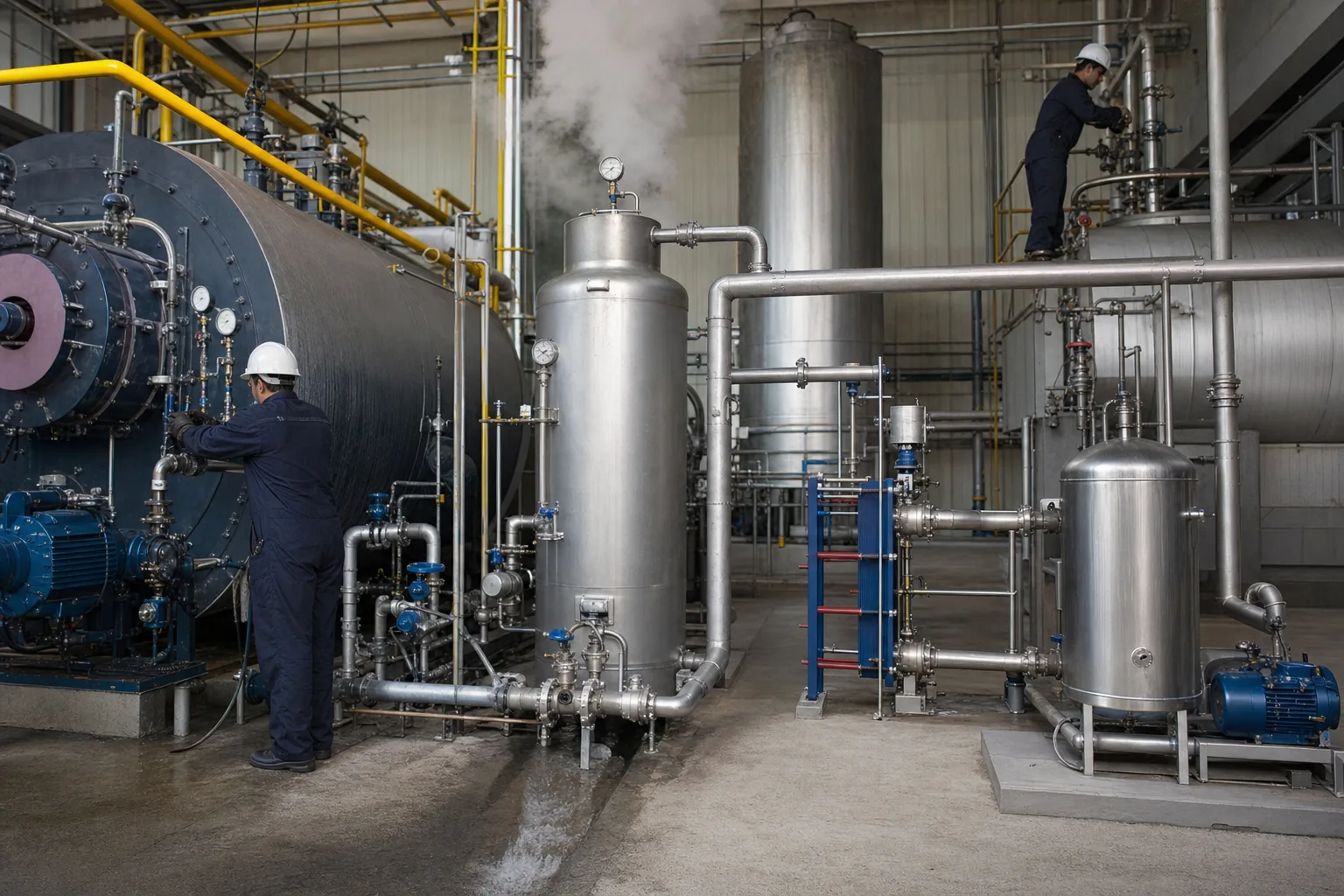 11Boiler and surface/bottom blowdown points22Blowdown flash-separation vessel33Plate heat exchanger for residual heat44Condensate receiver and return pump
What to identify
- 1Boiler and surface/bottom blowdown points
- 2Blowdown flash-separation vessel
- 3Plate heat exchanger for residual heat
- 4Condensate receiver and return pump
What this proves
Blowdown heat recovery reuses flash steam and sensible heat; condensate recovery returns the clean hot water itself. Their material boundaries differ.
Field check
Trace blowdown inlet, flash-steam outlet, residual liquid, both exchanger sides and receiver inlet/overflow/pump; verify check, trap, level, relief, isolation and burn protection.
A transparent flash rig shows vapor-liquid separation and sensible-heat transfer
Hot blowdown flashes in the lower-pressure vessel; vapor leaves above, while concentrated liquid enters the blue plate exchanger and indirectly heats a clean cold stream.
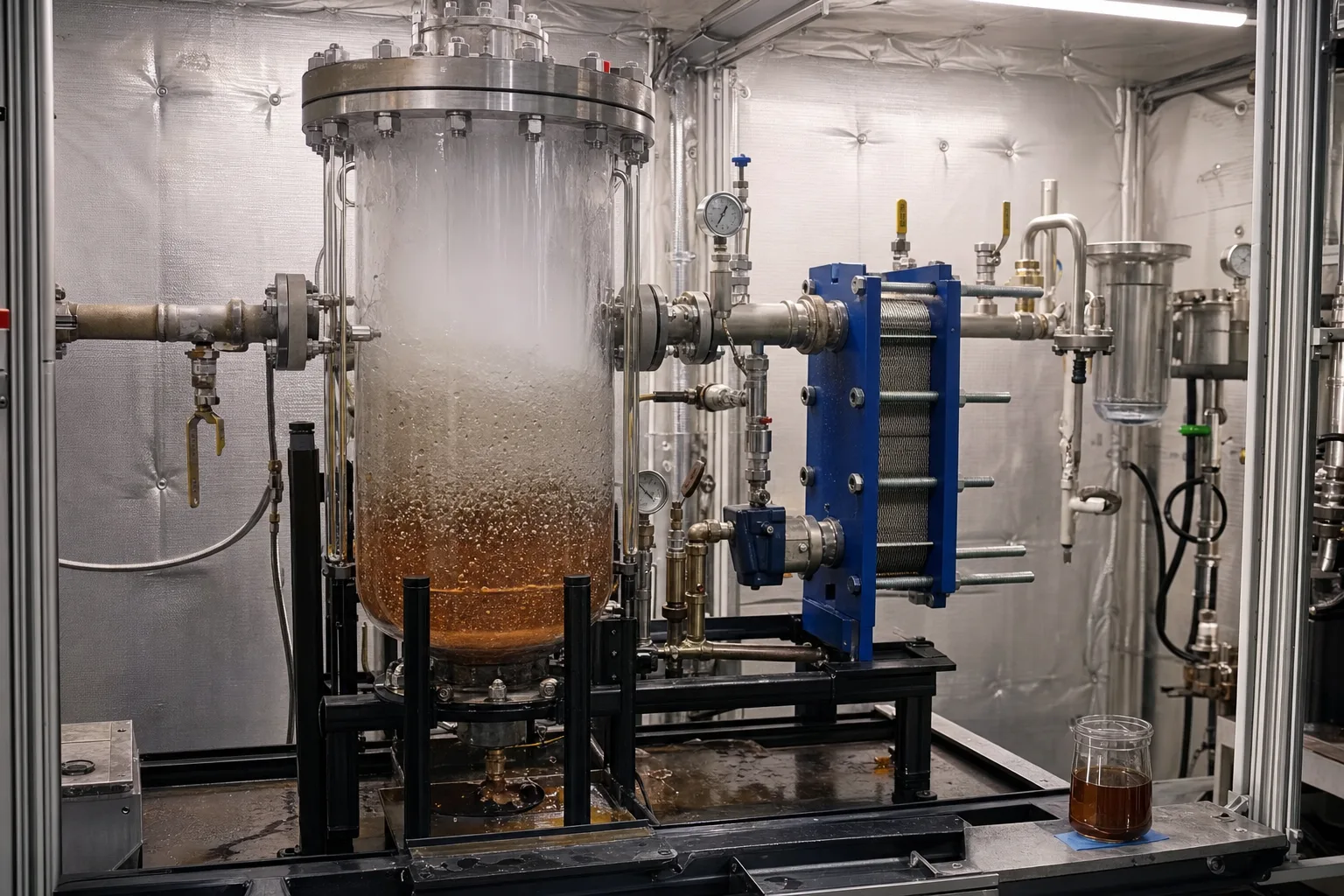 11Flashing bubbles and liquid interface22Upper low-pressure flash-steam space33Hot blowdown side of plate exchanger44Residual blowdown sample and chemistry
What to identify
- 1Flashing bubbles and liquid interface
- 2Upper low-pressure flash-steam space
- 3Hot blowdown side of plate exchanger
- 4Residual blowdown sample and chemistry
What this proves
Flashing does not vaporize the salts. Steam must be separated from droplets, and the remaining liquid retains both heat and concentrated impurities.
Field check
Measure upstream/downstream pressure-temperature-flow, steam destination, both exchanger side temperatures/DP and chemistry; inspect entrainment, level, fouling and cross-leakage.
A complete rig makes blowdown control, flashing, heat exchange, makeup and return measurable
The boiler supplies pressure, central valves/meters control blowdown, flash and plate units recover heat, and vessels/coils define the low-pressure load and return boundary.
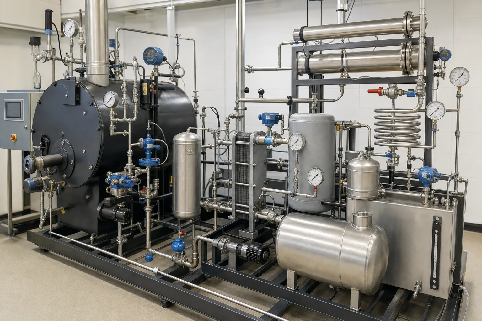 11Boiler and automatic blowdown valve/meter22Flash-vessel pressure and level control33Plate exchanger and cold-makeup circuit44Low-pressure load, receiver and flow meters
What to identify
- 1Boiler and automatic blowdown valve/meter
- 2Flash-vessel pressure and level control
- 3Plate exchanger and cold-makeup circuit
- 4Low-pressure load, receiver and flow meters
What this proves
Every mass flow, pressure, temperature and chemistry point must share one control volume. Equipment presence alone does not prove useful heat recovery.
Field check
At stable load, close steam-feed-blowdown-condensate balance; calculate enthalpy and verify makeup heating, lower deaerator steam or fuel, documenting bypasses and starts.
With multiple boilers, each unit needs independent blowdown measurement before common recovery
Boilers can have different loads and chemistry; individual instruments and valves control them before a common flash/heat-recovery skid combines energy.
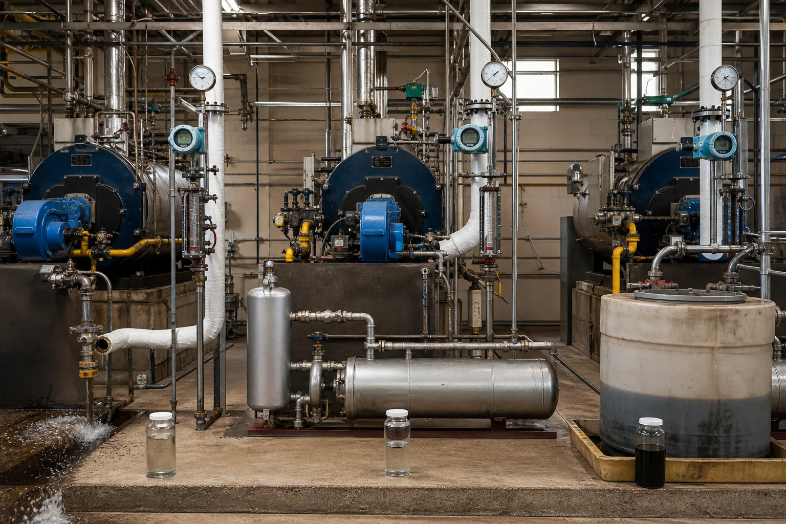 11Individual boiler load and blowdown boundary22Conductivity/flow instruments and valves33Common flash-heat-recovery equipment44Makeup, recovered and concentrated samples
What to identify
- 1Individual boiler load and blowdown boundary
- 2Conductivity/flow instruments and valves
- 3Common flash-heat-recovery equipment
- 4Makeup, recovered and concentrated samples
What this proves
One common valve cannot average-control different boilers. Unit-specific problems disappear in the total unless each boiler is measured first.
Field check
Verify representative samples, temperature-compensated conductivity, actual valve flow and load linkage per boiler; check common-vessel backpressure, reverse flow and sample identity.
Field sampling links exchanger, vessel, pump and water quality
Operators compare multiple cooled samples near a plate exchanger, horizontal vessel, valves and pump. Color is only a clue; chemistry and balance establish performance.
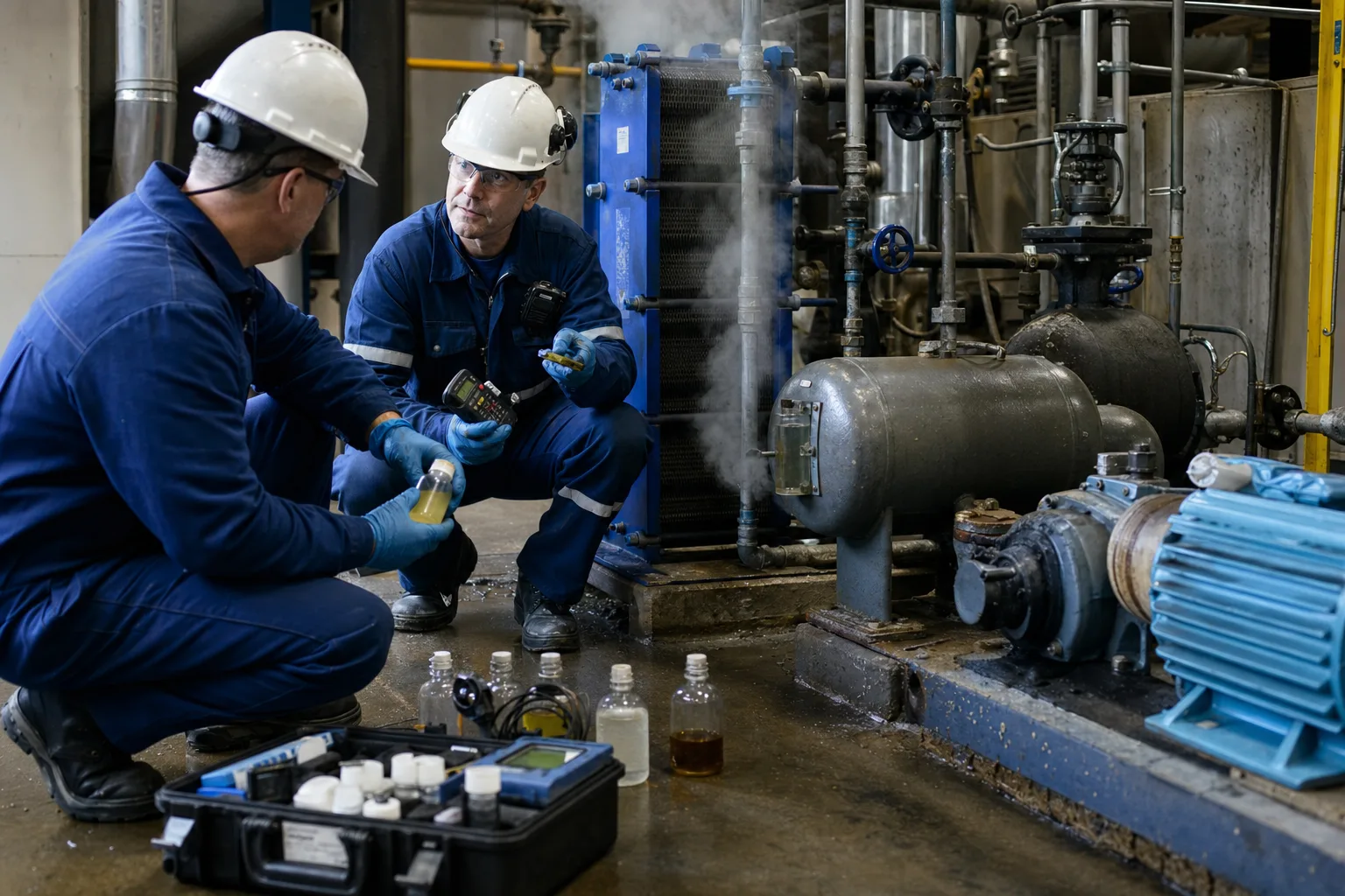 11Plate exchanger fouling/cross-leak point22Flash/receiver vessel pressure-level boundary33Return/circulation pump and valve condition44Identified samples and portable instruments
What to identify
- 1Plate exchanger fouling/cross-leak point
- 2Flash/receiver vessel pressure-level boundary
- 3Return/circulation pump and valve condition
- 4Identified samples and portable instruments
What this proves
Acceptance requires measurable useful heat, qualified recovered water, controlled boiler impurities and no exchanger cross-leak—not merely visible vapor or hot water.
Field check
Use LOTO and safe cooled sampling, record point/time/load, analyze conductivity, pH, hardness, silica/limiter and contaminants, then verify pump flow, approach temperature and leak pressure direction.
Eight-step water–impurity–heat loop
Separate what must leave from what can return and where heat is downgraded to useful loads.
1 Steam delivers heat
Boiler steam → process → hot condensate
The load receives latent heat; condensate retains sensible heat.
2 Trap and segregate
Condensate/noncondensables → trap; contaminated branch diverts
Prevent live-steam loss and protect return quality.
3 Return condensate
Qualified condensate → receiver/pressure return/pump → feedwater
Recover hot, treated, low-impurity water.
4 Monitor concentration
Feed impurities − steam carryover → boiler limiter
Set necessary blowdown from representative chemistry.
5 Blow down
Dissolved matter/sludge → surface/bottom removal
Protect deposition and steam purity.
6 Recover flash steam
Hot pressurized blowdown → lower pressure → steam + brine
Serve deaerator or compatible low-pressure load.
7 Recover sensible heat
Residual blowdown → exchanger → makeup preheat
Transfer heat while salt stays on blowdown side.
8 Verify three balances
Water + limiter + enthalpy/fuel
Prove all boundaries close together.
Four subsystems manage salt, water, heat and contamination
Recovery value depends on the boundary and the useful load, not temperature alone.
Blowdown control
- Primary role
- Maintain permitted concentration; surface removes dissolved matter and bottom removes sludge
- Failure/boundary
- Flashing samples, bad temperature compensation, fouled sensor, wrong valve flow or conductivity-only control
- Priority evidence
- Per-boiler feed/boiler chemistry, steam purity, actual flow, valve and load
Flash/heat recovery
- Primary role
- Split blowdown enthalpy into low-pressure steam and makeup preheat
- Failure/boundary
- Entrainment, backpressure, level, fouling, cross-leak or no useful load defeats recovery
- Priority evidence
- Port flows/P/T, steam destination, exchanger approach/DP, both-side chemistry and discharge T
Condensate return
- Primary role
- Recover hot low-impurity water and reduce makeup, treatment, chemicals and fuel
- Failure/boundary
- Traps, leaks, backpressure, insulation/pump failure or process contamination
- Priority evidence
- Branch flow/T/P/chemistry, trap survey, return rate and makeup change
Monitoring/diversion
- Primary role
- Detect oil, organics, acid/alkali or product leakage before the boiler
- Failure/boundary
- One slow header sample, no branch location or unsafe diversion state imports contamination
- Priority evidence
- Branch risk register, online/lab indicators, response time, diversion tests and destination
Flash fraction, recoverable heat and safe return fraction depend on actual pressure, temperature, flow, chemistry and available heat users. Calculate each system from measured data and steam properties; no universal blowdown or savings percentage applies.
Keep four matched-load data groups
Boiler and blowdown
Per-unit steam/load, feed and boiler limiters, compensated conductivity, actual surface/bottom flows, valve position, steam purity and events.
Flash and exchanger
Pre/post pressure-temperature-flow, steam destination/use, vessel level/backpressure, both-side exchanger flow, temperatures, DP, chemistry and discharge temperature.
Condensate and makeup
Branch condensate flow/T/P/quality, total return, makeup flow/T, traps/leaks, receiver overflow and pump performance.
Cost and equipment result
Fuel, treated water, salt/chemicals, discharge, feed temperature, deaerator steam, surface/steam quality, downtime and maintenance at normalized production.
Locate losses from inconsistent water, impurity and heat balances
- Signal
- Valve position is stable but boiler conductivity/silica and steam purity swing with load
- Priority hypothesis
- Sample/temperature error, changing valve capacity, feed quality or condensate fraction; fixed position is not fixed mass flow
- Next step
- Validate cooled sample/instrument and actual flow, then rebuild per-boiler load and impurity control
- Signal
- Flash vessel vents visibly but makeup temperature or low-pressure steam use does not improve
- Priority hypothesis
- Steam is wasted, backpressure/entrainment is wrong, heat user mismatched, or exchanger is bypassed/fouled
- Next step
- Measure all port flow/P/T and enthalpy, trace steam destination and inspect approach/DP/bypass
- Signal
- Return rate falls while makeup/fuel rise and the receiver vents or overflows
- Priority hypothesis
- Trap failure, return backpressure/pump limit, unmanaged flash, leak or inconsistent meters
- Next step
- Survey traps/leaks by branch, trend P/T/level/pump curve and close steam-return-makeup balance
- Signal
- Higher return is followed by foaming, TOC/conductivity upset or rapid fouling
- Priority hypothesis
- A leaking process exchanger or wrong branch imports contaminated condensate
- Next step
- Divert suspect branches under the protection procedure, sample by branch, test exchanger integrity and diversion interlock
Four common misconceptions
Less blowdown always saves energy
Below the chemistry/steam-quality requirement it creates deposits and carryover; the target is necessary minimum blowdown.
Hot blowdown should return to the boiler
Recover its heat across a wall or as flash steam; the concentrated liquid must still remove impurities.
All condensate is pure
Process leakage, corrosion products and air ingress require branch-specific risk management.
Visible flash steam proves recovery
Heat must enter a useful load and show in measured water/fuel balance with acceptable quality.