Solutions · Application Scenarios
Membrane fouling control: extending runs between cleans with data
Sensor-driven trending + cleaning science + pretreatment feedback loops. Longer productive intervals and lower irreversible fouling rates.
Use this guide within its scope
This page supports technical research and option comparison and is marked 2026. Illustrative values are not a quotation, completed process design, certification conclusion, or performance guarantee. Check current regulations, feed data, tests, and OEM records.
Problem
Plants clean on calendar time while fouling is non-linear.
Technology
Sensor-driven trending + cleaning science + pretreatment feedback loops.
Results
Longer productive intervals and lower irreversible fouling rates.
Engineering decision card
Use when
Plants clean on calendar time while fouling is non-linear.
Evaluate first
Sensor-driven trending + cleaning science + pretreatment feedback loops.
Inputs still required
Feed source and variability, capacity, target quality, operating hours, discharge or reuse boundary, available space, and utilities.
Comparison output
Longer productive intervals and lower irreversible fouling rates. The final decision still needs feed data, mass balance, and any necessary testing.
1. Process context & when this scenario is the right entry point
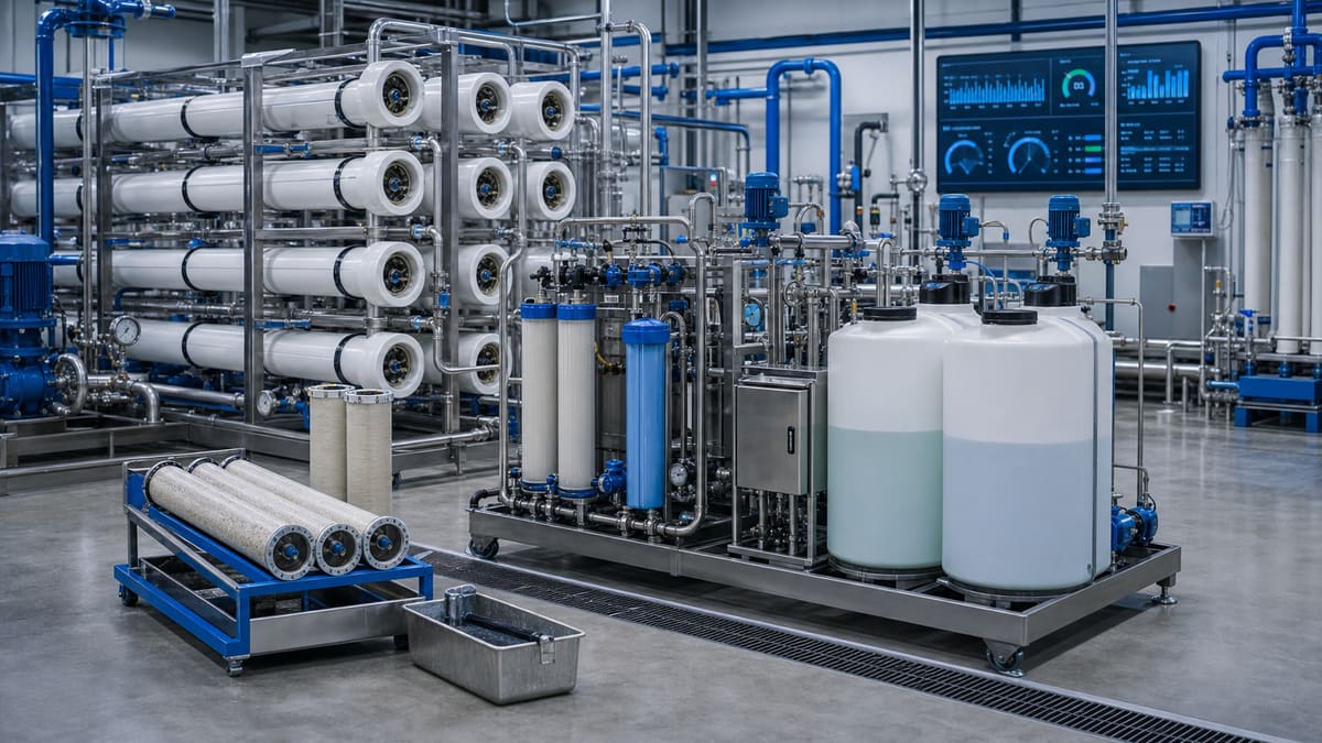
Membrane fouling is the primary operational challenge limiting the sustained performance and cost-effectiveness of reverse osmosis (RO) and nanofiltration (NF) systems. It manifests as a decline in normalized permeate flux at constant pressure, or an increase in transmembrane pressure (TMP) to maintain a constant flux, coupled with an increase in differential pressure (ΔP) across membrane stages. Untreated, fouling leads to higher energy consumption, reduced permeate production, increased frequency of costly chemical cleaning (CIP), shorter membrane lifespan, and ultimately, unscheduled downtime.
This scenario, focusing on proactive membrane fouling control, is the right entry point for any facility operating or planning to operate RO/NF systems, particularly those processing complex feedwaters such as surface water, treated municipal or industrial wastewater effluent, or challenging groundwater sources. The objective is to optimize membrane operation, extend cleaning intervals, minimize chemical usage, and maximize membrane life through advanced monitoring and data-driven decisions.
2. Feed characteristics & key risks
The susceptibility of a membrane system to fouling is largely dictated by its feed water quality. Key risks include:
- Particulate/Colloidal Fouling: Caused by suspended solids, silts, clays, and colloidal silica. Measured by SDI₁₅ (Silt Density Index), which indicates the rate at which a 0.45µm filter plugs. High SDI₁₅ values (>5 for RO) are strong indicators of potential particulate fouling.
- Organic Fouling: Due to natural organic matter (NOM), humic acids, fulvic acids, and synthetic organic compounds. These can adsorb onto the membrane surface, increasing hydrophobicity and reducing flux.
- Biological (Biofouling): Formation of biofilms by microorganisms (bacteria, algae, fungi) on the membrane surface, leading to a slimy layer that impedes flow. This is particularly prevalent in systems with insufficient biocide control or intermittent operation.
- Scaling (Inorganic Fouling): Precipitation of sparingly soluble salts like calcium carbonate, calcium sulfate, barium sulfate, silica, and strontium sulfate. The propensity for scaling is assessed by various saturation indices, with the LSI (Langelier Saturation Index) being common for calcium carbonate. Other indices (Stiff & Davis, Ryznar) or proprietary software are used for other salts. High positive LSI or supersaturation of other salts indicates scaling risk.
- Oxidative Damage: While not strictly fouling, oxidants like chlorine can damage polyamide membranes, leading to increased permeate conductivity and requiring membrane replacement. This is typically managed upstream of the RO/NF.
3. Concentrate / reject routing
Adhering to the principle of mass balance, the concentrate (also known as reject or brine) stream from the RO/NF system, rich in the impurities removed from the feed, must be managed responsibly. Its disposition directly impacts the overall economics and environmental footprint of the process. Typical routing strategies include:
- Regulated Discharge: Direct discharge to a permitted industrial sewer or surface water body, provided discharge limits (TDS, specific ion concentrations, metals, etc.) are met. This often requires pH adjustment and sometimes further polishing to meet regulatory compliance.
- Further Treatment for Recovery: The concentrate can become the feed for a subsequent, higher-pressure RO stage (e.g., a brine concentrator) or a nanofiltration (NF) system to recover additional water and further reduce concentrate volume. This increases overall system recovery.
- Evaporation/Crystallization: For Zero Liquid Discharge (ZLD) applications or when concentrate volumes are small but highly concentrated, the brine can be sent to evaporators and then crystallizers to recover salts as solids for disposal or potential beneficial reuse. This eliminates liquid discharge.
- Deep Well Injection: In regions where geology permits and regulations allow, high-TDS concentrates can be injected into deep, permeable geological formations, isolated from potable water sources.
- Industrial Reuse: In some cases, the concentrate, with its elevated TDS, might be suitable for less demanding industrial applications such as cooling tower makeup, dust suppression, or certain washing processes, subject to specific quality requirements.
- Return to Upstream Process: If the RO/NF system is treating a specific waste stream within a larger industrial complex (e.g., cooling tower blowdown, specific process rinse water), the concentrate might be recycled to an earlier stage of the overall plant's wastewater treatment or specific unit operation for further processing, provided it does not adversely affect that unit.
The choice of concentrate routing is dictated by feed water characteristics, permeate demand, cost, regulatory constraints, and the overall plant water balance strategy. Each option carries distinct capital and operational expenditure implications.
4. Reference process train options
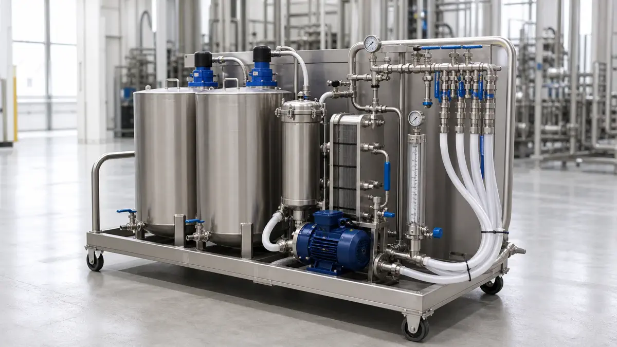
Effective membrane fouling control begins with robust pretreatment and extends through optimized RO/NF operation. A typical process train includes:
- Pretreatment:
- Coagulation/Flocculation & Clarification: For high-turbidity surface waters or wastewater effluents, to remove suspended solids, colloids, and some organic matter.
- Media Filtration: Multi-media filters (MMF) or dual-media filters (DMF) to remove larger suspended solids.
- Ultrafiltration (UF) or Microfiltration (MF): Increasingly common as superior pretreatment to RO/NF, providing a robust barrier against suspended solids, colloids, and microorganisms, ensuring consistent low SDI₁₅ (<1-3) to the RO/NF membranes.
- Chemical Dosing:
- Biocides: To control biological growth (e.g., sodium hypochlorite, followed by metabisulfite dechlorination).
- Dechlorination: Sodium bisulfite (SBS) or activated carbon filters to remove residual chlorine, protecting polyamide membranes.
- Anti-scalant: Dosed upstream of the RO/NF to inhibit the precipitation of scaling salts (e.g., calcium carbonate, sulfates, silica) by crystal distortion and dispersion.
- pH Adjustment: Acid (e.g., H₂SO₄) for calcium carbonate scaling control by shifting carbonate/bicarbonate equilibrium or caustic (e.g., NaOH) for silica solubility or specific metal precipitation.
- RO/NF System:
- Membrane Staging: Multi-stage designs (e.g., 2-stage, 3-stage) are used to achieve higher water recovery rates by feeding the concentrate from one stage to the next, while managing osmotic pressure and scaling potential. This optimizes membrane surface area utilization.
- Permeate Flux: Design flux (LMH) is chosen based on feed water quality, membrane type, and desired membrane life. Lower fluxes typically reduce fouling rates but require more membrane area. Typical industrial RO fluxes range from 10 to 30 L/(m²·h).
- CIP (Clean-In-Place) System: Essential for restoring membrane performance. Includes tanks, pumps, and piping for circulating cleaning solutions (acidic and alkaline) to dissolve and remove foulants.
5. Operating parameters
Precise control and monitoring of operating parameters are critical for proactive fouling management:
- SDI₁₅ Targets: For RO membranes, a feed SDI₁₅ of less than 5 is generally recommended, with targets of less than 3 preferred for high-recovery or sensitive applications. Continuous online SDI monitoring provides early warning of pretreatment excursions.
- LSI / Scaling Posture: The LSI and other scaling indices (e.g., for calcium sulfate, silica) are continuously calculated by the digital twin based on feed water chemistry, temperature, and recovery rate. Anti-scalant dosing is adjusted dynamically to maintain a non-scaling or inhibited-scaling condition at the concentrate-side of the membrane. Operating with a positive LSI can be managed effectively with proper anti-scalant selection and dosage, but careful monitoring is essential.
- Design Flux (LMH): The permeate flux rate, expressed as L/(m²·h), is a critical design and operational parameter. Operating at a higher flux generally increases the driving force for foulant deposition. Continuous monitoring of normalized flux (flux adjusted for temperature and pressure variations) is paramount. A sustained decline in normalized flux (>10-15%) typically indicates fouling and is a common trigger for CIP.
- Differential Pressure (ΔP): The pressure drop across an individual membrane stage, or more broadly, across the entire pressure vessel, is a key indicator of fouling. An increasing ΔP (e.g., a 15-20% increase over the clean pressure drop) signals increased flow resistance, often due to physical accumulation of foulants on the membrane surface or within the feed spacer channels, and is another strong trigger for CIP. Monitoring ΔP across each stage helps pinpoint the location of fouling within the array.
8. Common engineering mistakes & pilot KPIs
Common Engineering Mistakes:
- Underestimating Feed Water Variability: Designing for average conditions rather than extreme or fluctuating feed water quality often leads to inadequate pretreatment and rapid fouling.
- Ignoring Normalized Flux and ΔP Trends: Relying solely on permeate flow without normalizing or neglecting the crucial information provided by stage differential pressures.
- Overly Aggressive Flux Rates: Pushing membranes to higher fluxes to reduce capital cost per permeate unit often results in faster fouling, increased cleaning frequency, and shorter membrane life, leading to higher total cost of ownership.
- Inadequate Pretreatment Design: Insufficient removal of suspended solids, organics, or colloids from the feed water (e.g., SDI consistently above target).
- Improper CIP Execution: Not performing cleans when needed, using incorrect chemical concentrations, insufficient contact time, or improper cleaning sequence, leading to irreversible fouling.
- Assuming Anti-scalants are a Cure-all: While effective, anti-scalants have limitations. They do not eliminate the need for proper pH adjustment or robust pretreatment for particulate removal.
- Lack of Online Monitoring for Key Parameters: Not having continuous, reliable data for SDI₁₅, normalized flux, and stage ΔP prevents proactive intervention.
Key Performance Indicators (KPIs) for Pilot Studies:
- Normalized Flux Decline Rate: Expressed as % decline per day or week. This is the most direct measure of fouling rate under specific conditions.
- CIP Effectiveness: Measured by the percentage of normalized flux recovery after a CIP, and the stability of that recovery.
- Cleaning Frequency & Chemical Consumption: Indicating the operational burden and cost associated with fouling.
- Specific Energy Consumption (kWh/m³): Energy required to produce a unit volume of permeate, directly impacted by fouling (higher ΔP leads to higher pump energy).
- Concentrate Quality & Volume: To validate concentrate routing strategy and confirm recovery targets.
- Membrane Element Inspection: Physical inspection of pilot membranes after extended runs to visually assess fouling types and severity.
9. FAQ
Q2: Can I prevent all fouling? A2: Complete prevention of fouling is generally not economically or practically feasible. The goal is effective control and minimization to extend run times, maintain permeate quality, and reduce operational costs. Robust pretreatment, optimal chemical dosing (anti-scalant, biocide), and optimized operating parameters (e.g., lower flux) are key strategies.
Q3: What's the most critical parameter to monitor for fouling? A3: While several parameters are crucial, the most telling indicators are normalized permeate flux and differential pressure (ΔP) across stages. Normalized flux directly reflects the membrane's hydraulic performance adjusted for operating conditions, while ΔP indicates the buildup of foulants within the membrane element itself. Online SDI₁₅ also provides immediate insight into particulate fouling risk from the feed.
Related equipment & product lines
These categories typically support the approach above—open any line to compare brands and models.
- RO MembranesReverse osmosis membrane elements for municipal and industrial desalination.View category →
- Replacement Parts / SparesGeneral replacement parts for treatment systems and subassemblies.View category →
- Pilot Units TestingPilot rigs and trial modules for process validation and feasibility studies.View category →
For a closer review, use the engineering inquiry form to share feed, capacity, target, and project stage. Submission does not constitute a completed design or performance commitment.